Section 4 - Alignment & Calibration
4-25
Press <ESC> to stop calibration.
and moves the C-arm and the X-table back to their initial 0
°
positions.
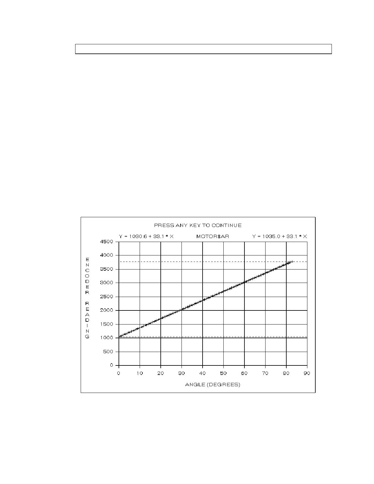
The program then switches to graphics mode and draws the Encoder Vs Angle calibration
grid. It steps the AR motor clockwise in 1
°
increments until the motor reaches the 83
°
position and then steps the AR motor counter clockwise in 1
°
increments until the motor
return to approximately 0
°
. The program plots the encoder data during the scan (in raw
encoder units, 0-4095).
Note:
Press
<ESC>
anytime during the scan to terminate the calibration procedure.
When the calibration scan completes, the program computes the linear fits to the positive and
negative rotation. The linear fit parameters are displayed at the top left and top right of the
plot in the form Y = Intercept + Slope * X. The two slopes should be within 1% of each
other.
The program displays the positive and negative limits as horizontal dashed lines
Note:
The
PosLimitOffset
and
NegLimitOffset
entries in the
[ArMotor]
section of the
hardware.ini
file determine the motion limits relative to the mechanical stops. If these
entries are not present, or are zero, the motion limits are set to the mechanical limits.
The program then changes the plot title to