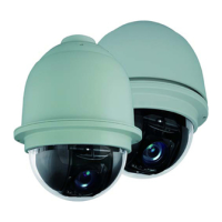
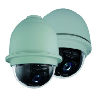
ACUIX™ PTZ High Speed Analog Dome Installation and Configuration Guide
Document 800-05662 Rev C 33
06/10
3
Installation
Note Review Installation Preparation, page 27 before continuing.
In this section:
• Installation Warnings and Cautions, page 33
• DIP Switch Default Settings and Locations, page 34
• Step 1: Set the Switches on the Housing Interface Board, page 36
• Step 2: Set the Switches on the Scan Assembly Circuit Board, page 40
• Step 3: Install the Mount, Adapter or Bracket, page 43
• Step 4: Install the Housing, page 50
• Step 5: Connect the Field and Terminal Block Wiring, page 54
• Step 6: Install the Scan Assembly into the Housing, page 58
• Step 7: Install the Lower Dome onto the Housing, page 59
• Step 8: Configure the Dome, page 61
Installation Warnings and Cautions
WARNING! All installations must be performed by qualified technical
personnel and must be in accordance with all national and
local mechanical and electrical codes.
Ensure the mounting surface and installation hardware can
hold the combined weight of the scan assembly, housing,
lower dome and mount.
To prevent damage to the interface board, follow standard
industry precautions for electrostatic discharge-sensitive
devices.
 Loading...