ACUIX™ PTZ High Speed Analog Dome Installation and Configuration Guide
Document 800-05662 Rev C 55
06/10
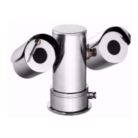
Figure 3-19 Terminal Blocks J6 (Data) and J7 (Video)
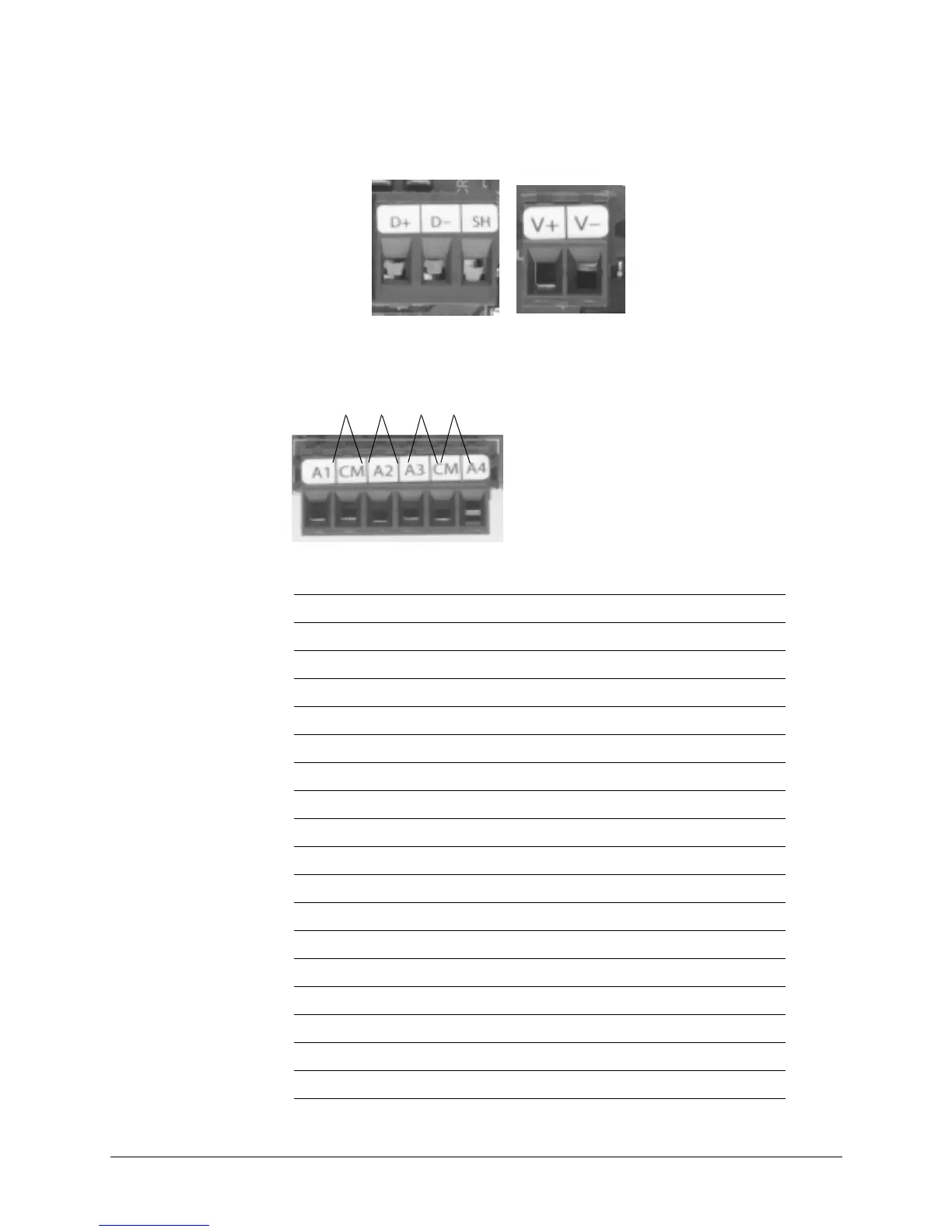
Figure 3-20 Terminal Block J4 (Contacts)
J6
RS485 Data
Wiring
J7
UTP Wiring
Contact 1
Contact 2
Contact 3
Contact 4
Table 3-8 Terminal Strip Pins and Functions (J1, J4, J6 and J7)
Terminal Strip J1 Function
Pin 1 24 VAC input A
Pin 2 ESD (electrostatic discharge) grounding
Pin 3 24 VAC input B
Terminal Strip J4 Function
Pin 1 Contact 1 (A1)
Pin 2 Contact common (CM)
Pin 3 Contact 2 (A2)
Pin 4 Contact 3 (A3)
Pin 5 Contact common (CM)
Pin 6 Contact 4 (A4)
Terminal Strip J6 Function
Pin 1 RS485 data (+) communication signal
Pin 2 RS485 data (-) communication signal
Pin 3 Shield (SH)
Terminal Strip J7 Function
Pin 1 Video + (V+) (UTP wiring)
Pin 2 Video – (V–) (UTP wiring)
 Loading...