ACUIX™ PTZ High Speed Analog Dome Installation and Configuration Guide
Document 800-05662 Rev C 47
06/10
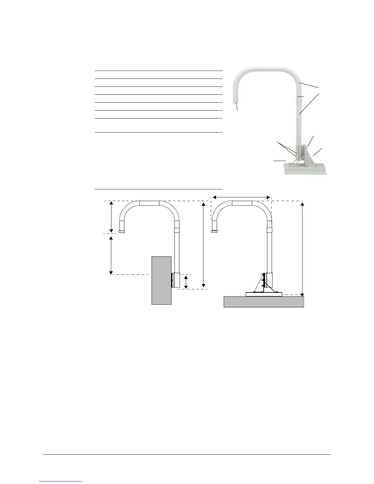
Figure 3-10 Parapet and Roof Mount Parts and Dimensions
Installing a Ceiling Mount
For both indoor and outdoor pendant housings, the ceiling mount is installed directly to
a horizontal load-bearing surface and supports up to 25 pounds (11.7 kg).
1. Route field wiring as required into the dome wiring access hole and through the
center of the ceiling mount.
Approximately one foot (0.3 m) of cable must extend past the mount.
2. Secure the ceiling mount to the ceiling using hardware specifically designed for the
surface.
There are four 0.47” (12.00 mm) diameter mounting holes for securing the mount.
See Figure 3-11.
1 Nut and socket
2 Mounting arm (2 pc)
3Coupling (x1)
4 Base plate (x1)
5 Support angle (x2)
6 Bracket angle (x1)
7
Hexagon head bolt, nuts and spring
washers M10 (x12
Not shown
Panhead screw M4 x 8 (x2)
Set screw M5 x 6 (x3)
Wrench head bolt M6 x 30 (x3)
Pipe fastener (x1)
Hexagon nut M6 (x3)
HEX Allen wrench, 2.5 mm (x1)
HEX Allen wrench, 5 mm (x1)
Flat washer M10 (x12)
Teflon seal tape (x1)
2
3
1
4
5
6
7
24.72” (628 mm)
39.60” (1006 mm)
Parapet
Roof
12.20” (310 mm)
35.83”
(910 mm)
5.9”
(150 mm)
17.71” (450 mm)
 Loading...