SW5
SW6
Printed circuit board location
(PCB) on top of the scan assembly
Scan assembly
(includes camera)
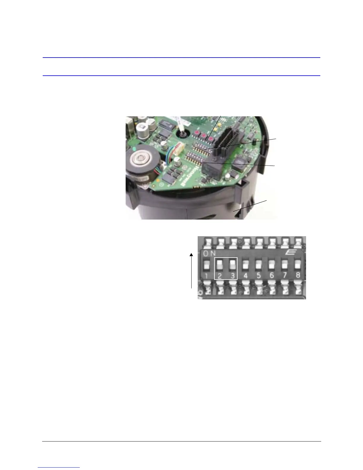
ON
OFF
Positions 2, 3 set ON
Positions 1, 4, 5, and 6 set OFF
Example of a SW6 DIP switch setting
38400 baud rate and no parity
1
2
SW1, 2, 3, and 4 dome address
settings (for ACUIX analog only)
 Loading...