HT2800T_en_c.doc Page 235 of 275
Figure 188: Exploded view of the syringe warmer assembly
1 Main screws
2 Upper cover
3 Syringe plunger
4 Heating body
5 Insulating gasket
6 Syringe holder
7 Upper spacer
8 Syringe barrel
9 Lower spacers
Proceed as described below:
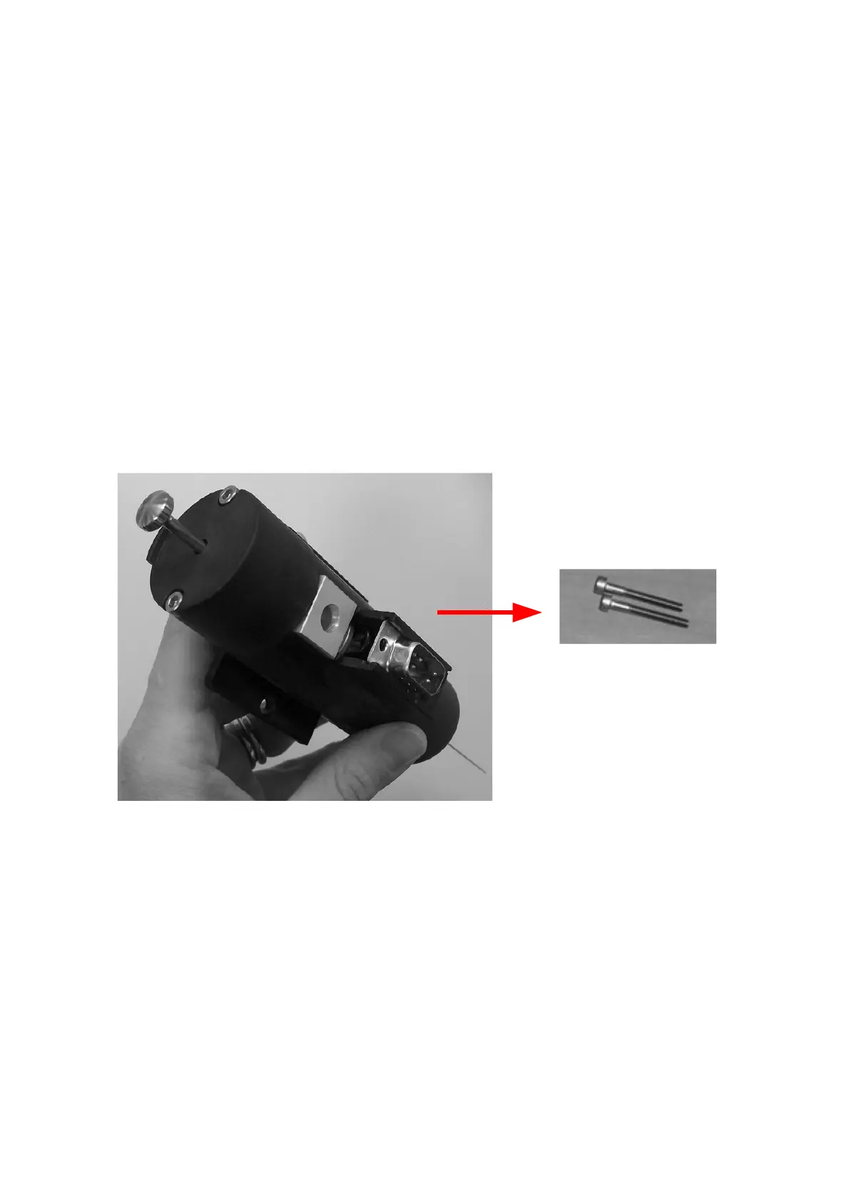
1) Remove the two main screws (number 1 in figure below) that secure the upper
cover using the supplied allen key (see paragraph 2.3 “Tool kit“).
Figure 189: Main screw
2) Gently lift up the upper cover (number 2 in figure below) and the syringe plunger
(number 3 in in figure below )to detach them from the heating body (number 4 in figure
below).