l Switch B functions as an NTP time server. That is, Switch A synchronizes its clock with
that of Switch B.
l One-way transmission of data packets between Switch A and Switch B takes one second.
l Processing of data packets on the Switch A or theSwitch B takes one second.
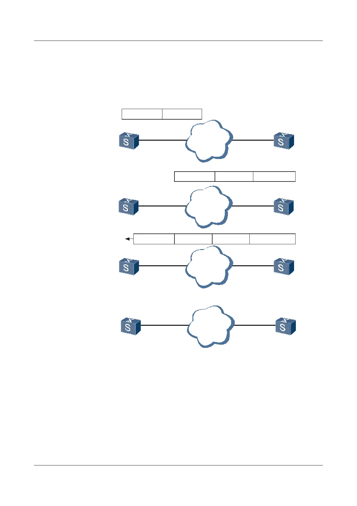
Figure 4-1 NTP basic principle diagram
SwitchA
Network
SwitchB
Step 1:
NTP packet 10:00:00am
SwitchA
Network
SwitchB
Step 2:
NTP packet 10:00:00am
SwitchA
Network
SwitchB
Step 3:
SwitchA
Network
SwitchB
Step 4:
11:00:01am
NTP packet 10:00:00am 11:00:02am11:00:01am
NTP packet received at
10:00:03
The process of synchronizing system clocks is as follows:
1. Switch A sends an NTP packet to Switch B. The packet carries the originating timestamp
when it leaves Switch A, which is 10:00:00 am (T1).
2. When the NTP packet reaches Switch B, Switch B adds its receiving timestamp to the NTP
packet, which is 11: 00:01 am (T2).
3. When the NTP packet leaves Switch B, Switch B adds its transmitting timestamp to the
NTP packet, which is 11:00:02 am (T3).
4. When Switch A receives the response packet, it adds a new receiving timestamp to it, which
is 10:00:03 am (T4).
Quidway S5700 Series Ethernet Switches
Configuration Guide - Network Management 4 NTP Configuration
Issue 01 (2011-10-26) Huawei Proprietary and Confidential
Copyright © Huawei Technologies Co., Ltd.
211

 Loading...