6.27.15 Example for Configuring the PWE3 Ping Test on a Multi-
Hop PW
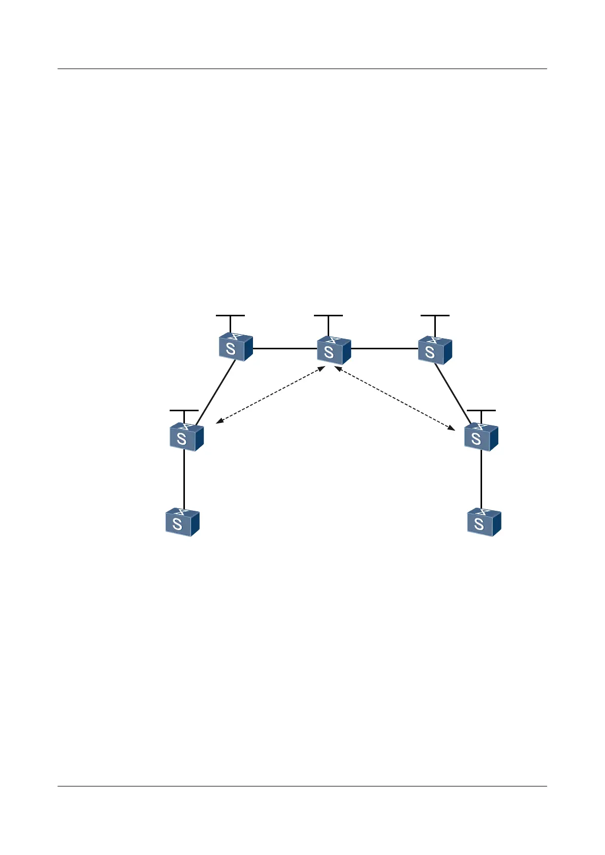
Networking Requirements
As shown in Figure 6-17, CE-A and CE-B are connected to U-PE1 and U-PE2 respectively
through PPP. U-PE1 and U-PE2 are connected through the MPLS backbone network. The LSP
needs to be used and S-PE is set as the switching node to set up a dynamic multi-hop PW between
U-PE1 and U-PE2.
The PWE3 Ping function of the multi-hop PW needs to be performed to test the connectivity of
the PW between U-PE1 and U-PE2.
Figure 6-17 Networking diagram for configuring the PWE3 Ping test on a multi-hop PW
CE-A CE-B
U-PE1
GE0/0/1
VLANIF110
100.1.1.1/24
GE0/0/1
GE0/0/1
VLANIF160
100.1.1.2/24
U-PE2
S-PE
GE0/0/2
VLANIF130
20.1.1.1/24
GE0/0/1
VLANIF130
20.1.1.2/24
GE0/0/1
VLANIF150
VLANIF120
10.1.1.2/24
GE0/0/1
VLANIF120
10.1.1.1/24
Loopback0
3.3.3.9/32
Loopback0
2.2.2.9/32 4.4.4.9/32
Loopback0
1.1.1.9/32
Loopback0
5.5.5.9/32
VLANIF140
30.1.1.1/24
GE0/0/2
VLANIF140
30.1.1.2/24
GE0/0/2
VLANIF150
40.1.1.1/24
GE0/0/2
40.1.1.2/24
P1 P2
Loopback0
GE0/0/1
VLANIF110
GE0/0/2
VLANIF160
P
W
1
0
0
P
W
2
0
0
Configuration Roadmap
The configuration roadmap is as follows:
1. Run the IGP protocol on the backbone network to make the routes between Switches on
the backbone network reachable.
2. Configure the basic MPLS functions on the backbone network and set up an LSP tunnel.
Set up MPLS LDP peer relations between U-PE1 and S-PE, and between U-PE2 and S-
PE.
3. Create an MPLS L2VC connection between the two U-PEs.
4. Create a switching PW on the switching node S-PE.
5. Configure a PWE3 Ping test on the multi-hop PW on U-PE1.
Quidway S5700 Series Ethernet Switches
Configuration Guide - Network Management 6 NQA Configuration
Issue 01 (2011-10-26) Huawei Proprietary and Confidential
Copyright © Huawei Technologies Co., Ltd.
369

 Loading...