port hybrid untagged vlan 110
#
nqa-server udpecho 10.2.1.2 9000
#
ip route-static 10.1.1.0 255.255.255.0 10.2.1.1
#
return
6.27.11 Example for Configuring the LSP Ping Test for a Common
Tunnel
Networking Requirements
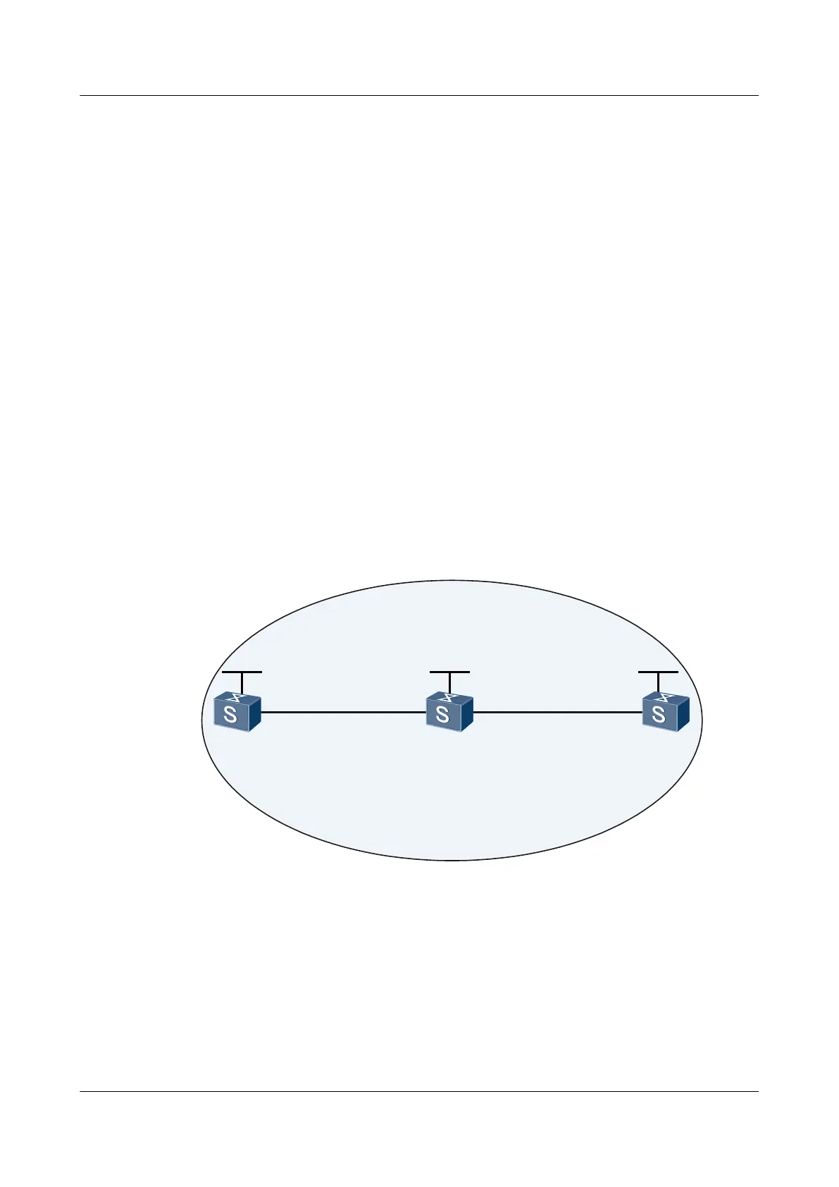
As shown in Figure 6-13:
l The OSPF protocol runs on Switch A, Switch B, and Switch C. The three Switches learn
the 32-bit host routes on their loopback interfaces.
l MPLS and MPLS LDP are enabled on Switch A, Switch B, and Switch C.
l MPLS and MPLS LDP are enabled on VLANIF interfaces connected to Switch A,
Switch B, and Switch C to trigger the establishment of an LDP LSP.
The NQA LSP Ping test needs to be performed to check the connectivity of the LSP between
Switch A and Switch C.
Figure 6-13 Networking diagram for configuring the LSP Ping test
VLANIF110
10.2.1.1/24
GE0/0/2
SwitchA
GE0/0/1
VLANIF100
10.1.1.1/24
GE0/0/1
VLANIF100
10.1.1.2/24
area 0
Loopback1
1.1.1.9/32
Loopback1
2.2.2.9/32
Loopback1
3.3.3.9/32
GE0/0/2
VLANIF110
10.2.1.2/24
SwitchB
SwitchC
Configuration Roadmap
The configuration roadmap is as follows:
1. Configure Switch A as the NQA client.
2. Configure Switch C as the NQA server.
3. Create an LSP Ping test on Switch A.
Quidway S5700 Series Ethernet Switches
Configuration Guide - Network Management 6 NQA Configuration
Issue 01 (2011-10-26) Huawei Proprietary and Confidential
Copyright © Huawei Technologies Co., Ltd.
356

 Loading...