#
mpls lsr-id 3.3.3.9
mpls
#
mpls ldp
#
interface Vlanif110
ip address 10.2.1.2 255.255.255.0
mpls
mpls ldp
#
interface GigabitEthernet0/0/1
port hybrid pvid vlan 110
port hybrid untagged vlan 110
#
interface LoopBack1
ip address 3.3.3.9 255.255.255.255
#
ospf 1
area 0.0.0.0
network 3.3.3.9 0.0.0.0
network 10.2.1.0 0.0.0.255
#
return
6.27.12 Example for Configuring the LSP Jitter Test for a Common
Tunnel
Networking Requirements
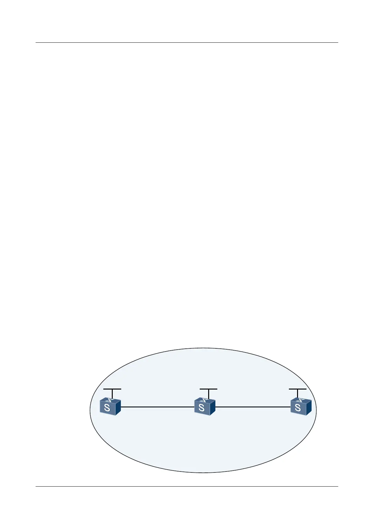
As shown in Figure 6-14:
l The OSPF protocol runs on Switch A, Switch B, and Switch C. The three Switches learn
the 32-bit host routes on their loopback interfaces.
l MPLS and MPLS LDP are enabled on Switch A, Switch B, and Switch C.
l MPLS and MPLS LDP are enabled on VLANIF interfaces connected to Switch A,
Switch B, and Switch C to trigger the establishment of an LDP LSP.
The NQA LSP Ping test is used to check the connectivity of the LSP between Switch A and
Switch C.
Figure 6-14 Networking diagram for configuring the LSP Jitter test
VLANIF110
10.2.1.1/24
GE0/0/2
SwitchA
GE0/0/1
VLANIF100
10.1.1.1/24
GE0/0/1
VLANIF100
10.1.1.2/24
area 0
Loopback1
1.1.1.9/32
Loopback1
2.2.2.9/32
Loopback1
3.3.3.9/32
GE0/0/1
VLANIF110
10.2.1.2/24
SwitchB
SwitchC
Quidway S5700 Series Ethernet Switches
Configuration Guide - Network Management 6 NQA Configuration
Issue 01 (2011-10-26) Huawei Proprietary and Confidential
Copyright © Huawei Technologies Co., Ltd.
359

 Loading...