#
interface GigabitEthernet0/0/1
port hybrid pvid vlan 140
port hybrid untagged vlan 140
#
return
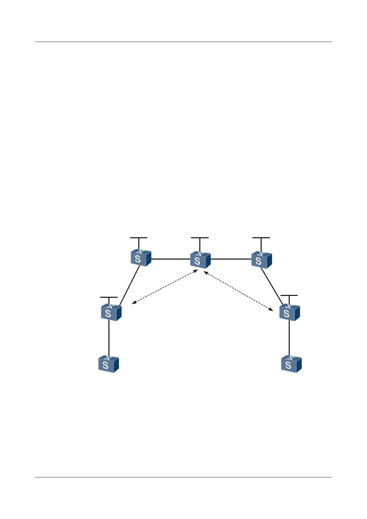
6.27.17 Example for Configuring the PWE3 Trace Test on a Multi-
Hop PW
Networking Requirements
As shown in Figure 6-19, CE-A and CE-B are respectively connected to U-PE1 and U-PE2
through PPP. U-PE1 and U-PE2 are connected through the MPLS backbone network. The LSP
needs to be used and S-PE is set as the switching node to set up a dynamic multi-hop PW between
U-PE1 and U-PE2.
The PWE3 Trace function of the multi-hop PW needs to be performed to test the connectivity
of the PW between U-PE1 and U-PE2.
Figure 6-19 Networking diagram for configuring the PWE3 Trace test on a multi-hop PW
CE-A CE-B
U-PE1
GE0/0/1
VLANIF110
100.1.1.1/24
GE0/0/1
GE0/0/1
VLANIF160
100.1.1.2/24
U-PE2
S-PE
GE0/0/2
VLANIF130
20.1.1.1/24
GE0/0/1
VLANIF130
20.1.1.2/24
GE0/0/1
VLANIF150
VLANIF120
10.1.1.2/24
GE0/0/1
VLANIF120
10.1.1.1/24
Loopback0
3.3.3.9/32
Loopback0
2.2.2.9/32 4.4.4.9/32
Loopback0
1.1.1.9/32
Loopback0
5.5.5.9/32
VLANIF14
0
30.1.1.1/24
GE0/0/2
VLANIF140
30.1.1.2/24
GE0/0/2
VLANIF150
40.1.1.1/24
GE0/0/2
40.1.1.2/24
P1 P2
Loopback0
GE0/0/1
VLANIF110
GE0/0/2
VLANIF16
0
P
W
1
0
0
P
W
2
0
0
Configuration Roadmap
The configuration roadmap is as follows:
1. Run the IGP protocol on the backbone network to make the routes between Switches on
the backbone network reachable.
Quidway S5700 Series Ethernet Switches
Configuration Guide - Network Management 6 NQA Configuration
Issue 01 (2011-10-26) Huawei Proprietary and Confidential
Copyright © Huawei Technologies Co., Ltd.
379

 Loading...