O.9Part. N. 8000 H1344 (10-2009)
“KIT” ASSEMBLING INSTRUCTIONS
6- Blinkers Kit (SMR)
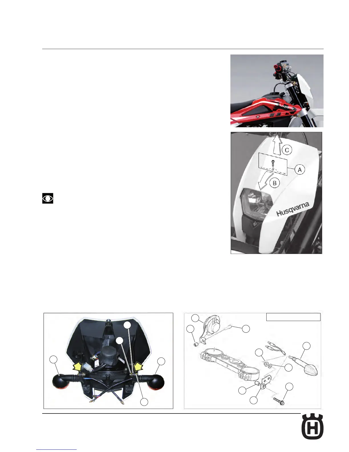
FRONT TURN SIGNALS
Remove the upper fastening screw of the the headlamp carrier to the
instrument panuel support (A);
- push forward the headlamp carrier (B) and pull it towards the high (C) in
order to uncouple from the two lower supports.
- remove the headlamp carrier and x over it the blinkers using the nuts (3).
Reassemble the headlamp carrier with the assembled blinkers linking the
blinkers to the mail cable harness (follow the electrical schema at page O. 15).
U.S.A. Models
Remove the headlamp carrier as described above.
Assemble the turn signal (1) on the plate (4) fastening with the nut (6) M6, then
pass the cable (B) trough the plate front hole. Remove the steering head fasten-
ing screws (B) and assemble the plate complete with turn signal using the same
screws (4) and the corresponding spacer (5) (R.H. side: remember to assemble
the horn (C) too, between the turn signal plate and the steering head). Connect
the turn signals to the main wiring harness. Regarding the correct connection to
the main wiring harness, see the wiring diagram (page O.13).
The description refers to the assembly of the left turn signal (1), the as-
sembly of the right turn signal is symmetrical.
BLINKERS KIT
1- Front left and rear right turn signal (2)
2- Rear left and front right turn signal (2)
3- Nut M8 (4)
4- Elastic washer Ø8 (4)
5- Flasher (1)
6- Flasher support bracket (1)
E
C
B
1
4
3
B
E
D
2
B
3
1
4
U.S.A. MODELS