6. Parameter
6.1 Parameter
6-49
ME0342-4B
[90] Minor Trouble Alarm Output Select (Parameter No. 151)
No. Name Unit Input range
Default initial value setting
151
Minor trouble alarm
output select
-
0: Overload warning
output
1: Message level alarm
1
Select the output condition of *ALML Signal
(Note 1)
.
If 0 is set, when parameter No. 143 “Overload Load Level Ratio” is exceeded, the minor
malfunction alarm signal *ALML will be output.
If 1 is set, when a message level alarm is generated, *ALML signal will be output.
Note1 In PIO Patterns 0 or from 2 to 4, Parameter No. 156 should be changed to 1, and
LOAD/TRQS Signals should be switched to *ALML Signal.
[91] High Output Setting (Parameter No.152)
No. Name Unit Input range
Default initial value setting
152 High output setting -
0: Disabled
1: Enabled
In accordance with actuator
Set if high output function is to be used. However, it is necessary to connect an actuator
(Note 1)
that supports high output.
Note 1 RCP4, RCP5 and RCP6 Series
[92] BU Velocity Loop Proportional Gain (Parameter No. 153)
No. Name Unit Input range
Default initial value setting
153
BU velocity loop
proportional gain
- 1 to 99,999,999 In accordance with actuator
When Parameter No. 152 “High Output Setting” is enabled and Parameter No. 144 “GS
Magnification Upper Limit” is set to 100 or less, the setting of this parameter is enabled for
Velocity Loop Proportional Gain.
For details, refer to [6.1.2 [24] Velocity Loop Proportional Gain (Parameter No. 31)].
For the conditions for using this item, refer to [Reference in [6.1.2 [25] Selection and use of
Velocity Loop Proportional Gain and Velocity Loop Integral Gain].
6.1 Parameter
ME0342-4B 6-50
[93] BU Velocity Loop Integral Gain (Parameter No. 154)
No. Name Unit Input range
Default initial value setting
154
BU velocity loop integral
gain
- 1 to 99,999,999 In accordance with actuator
When Parameter No. 152 “High Output Setting” is enabled and Parameter No. 144 “GS
Magnification Upper Limit” is set to 100 or less, the setting of this parameter is enabled for
Velocity Loop Integral Gain.
For details, refer to [6.1.2 [25] Velocity Loop Integral Gain (Parameter No. 32)].
For the conditions for using this item, refer to [Reference in [6.1.2 [25] Selection and use of
Velocity Loop Proportional Gain and Velocity Loop Integral Gain].
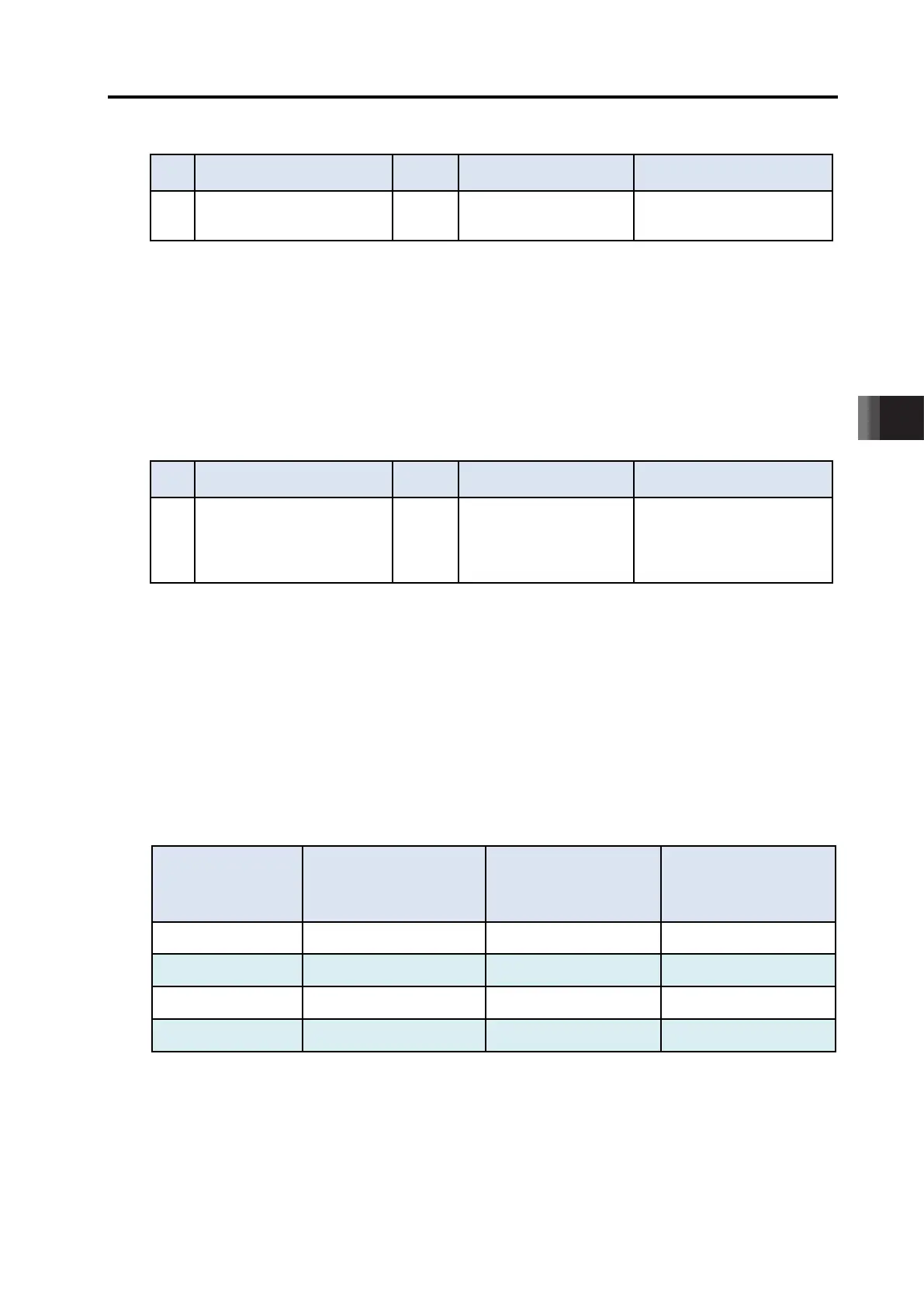
[94] ABS Battery Retaining Time (Parameter No. 155) …Positioner only
No. Name Unit Input range
Default initial value setting
155 ABS battery retaining time
-
0: 20 days
1: 15 days
2: 10 days
3: 5 days
0
This function is limited to the simple absolute specification. Set encoder positional data retention
time after turning the power supply to the actuator OFF. The setting is available in 4 levels. The
lower the motor rotation speed setting is, the longer the retention time of the positional data can
be. If there is a possibility of external force moving the workpiece conveying components of the
actuator such as the slider or rod while power is OFF, refer to the following table and calculate
motor revolution based on movement speed and set the value of this parameter faster. If the
motor revolution exceeds the set value, positional data will be lost.
The motor rotation speed can be calculated with the equation below.
Motor revolution [r/min] = Movement speed [mm/s] / Actuator lead [mm] x 60 [s/min]
For details, refer to "4.5.2 Absolute Battery Charge".
Parameter No.155
settings
rotation speed
when power is OFF
Battery retaining
time guideline [days]
hour of charge time
(guideline)
0 100 20 6.6
1 200 15 5.0
2 400 10 3.3
3 800 5 1.6

 Loading...


