9. Appendix
9.3 Example of Basic Positioning Sequence (PIO pattern 0 to 3)
9-28 ME0342-4B
[10] Position 3 Operation Circuit
The main circuit is designed to process and manage signals “start” → “moving” → “positioning
complete” to move the actuator to position No.3. This circuit indicates the same sequence as
that of position No.1.
9.3 Example of Basic Positioning Sequence (PIO pattern 0 to 3)
ME0342-4B 9-29
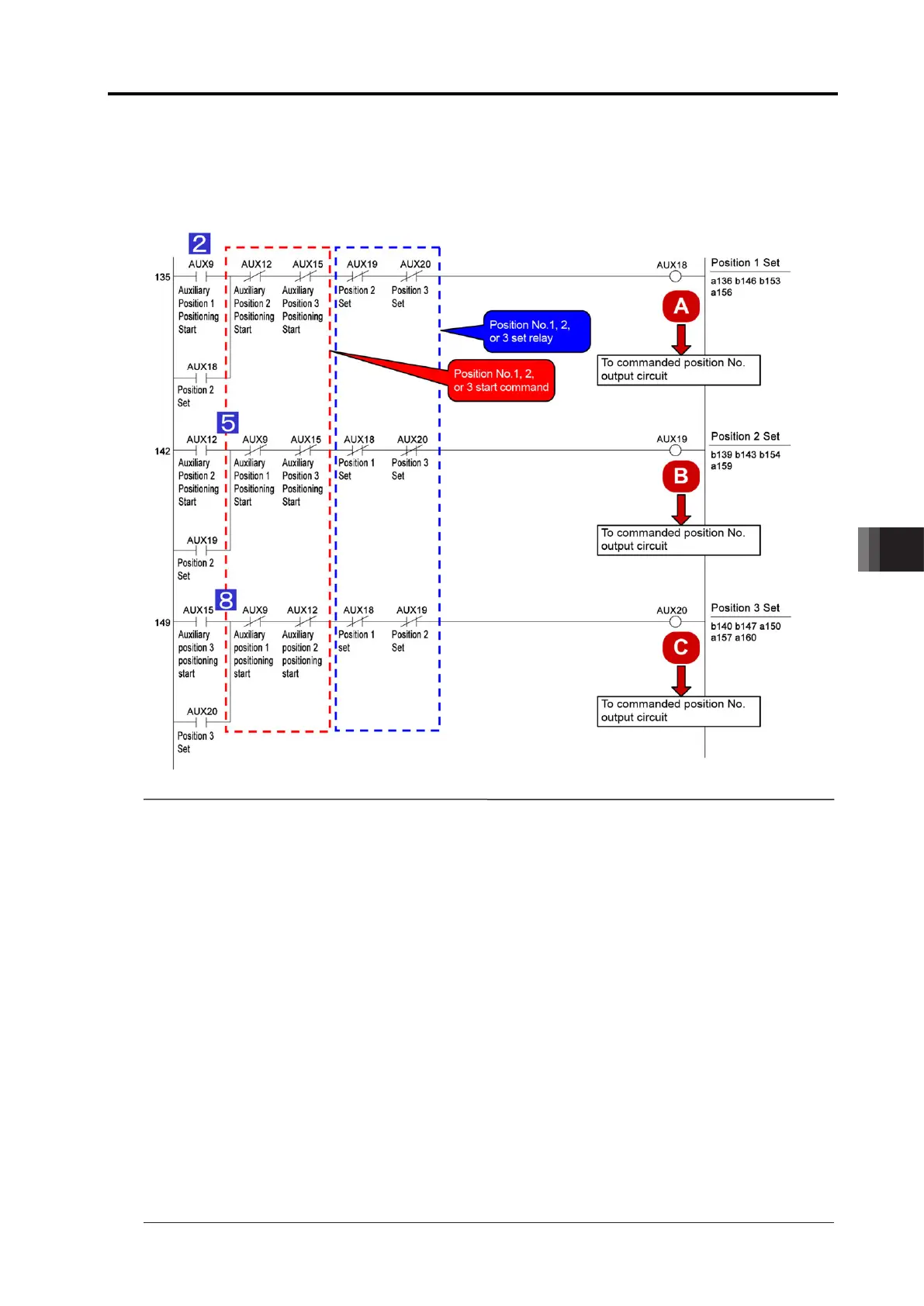
[11] Commanded Position No. Output Ready Circuit
The ready circuit is designed to hold start command and output commanded position No. in the
binary code.
Interlock is taken so that position No. command may not be specified incorrectly.
Point!
● Once a moving command to a position is issued, any of circuits A, B and C is turned on,
and the current command should be remembered unless a moving command to another
position is issued. The operation circuit is cancelled by a stop command such as an
emergency stop command. However, the circuit remembers the positions to which the
actuator moved and the positions at which the actuator stopped until the cancellation.
Such sequence design is also intended to cope with errors occurred and helpful to find
the causes of the errors from circuit status, stop position inconsistency and other
conditions.
●
Taking interlock in both commands and results is usual means in circuit design to prevent
results from being ON simultaneously. For example, if both SOLs in a solenoid valve of
double SOL type are turned ON simultaneously, the coils are burned instantly. In another
case, PLC executes a program in descending order but operations are not always done
in the order. If you create a sequence program taking operation order into account, circuit
change and/or addition due to debugging and specification change may cause the
operation order to be modified without intention. Take interlock securely.

 Loading...


