Programming IDEC SmartRelay
3.9 Memory space and circuit program size
IDEC SmartRelay Manual
106
CAUTION
At a power failure, the logical input level may drop to zero before IDEC SmartRelay can save
the functions to the retentive memory. In this case, the IDEC SmartRelay saves the function
values determined by the zero state at its inputs of the inputs.
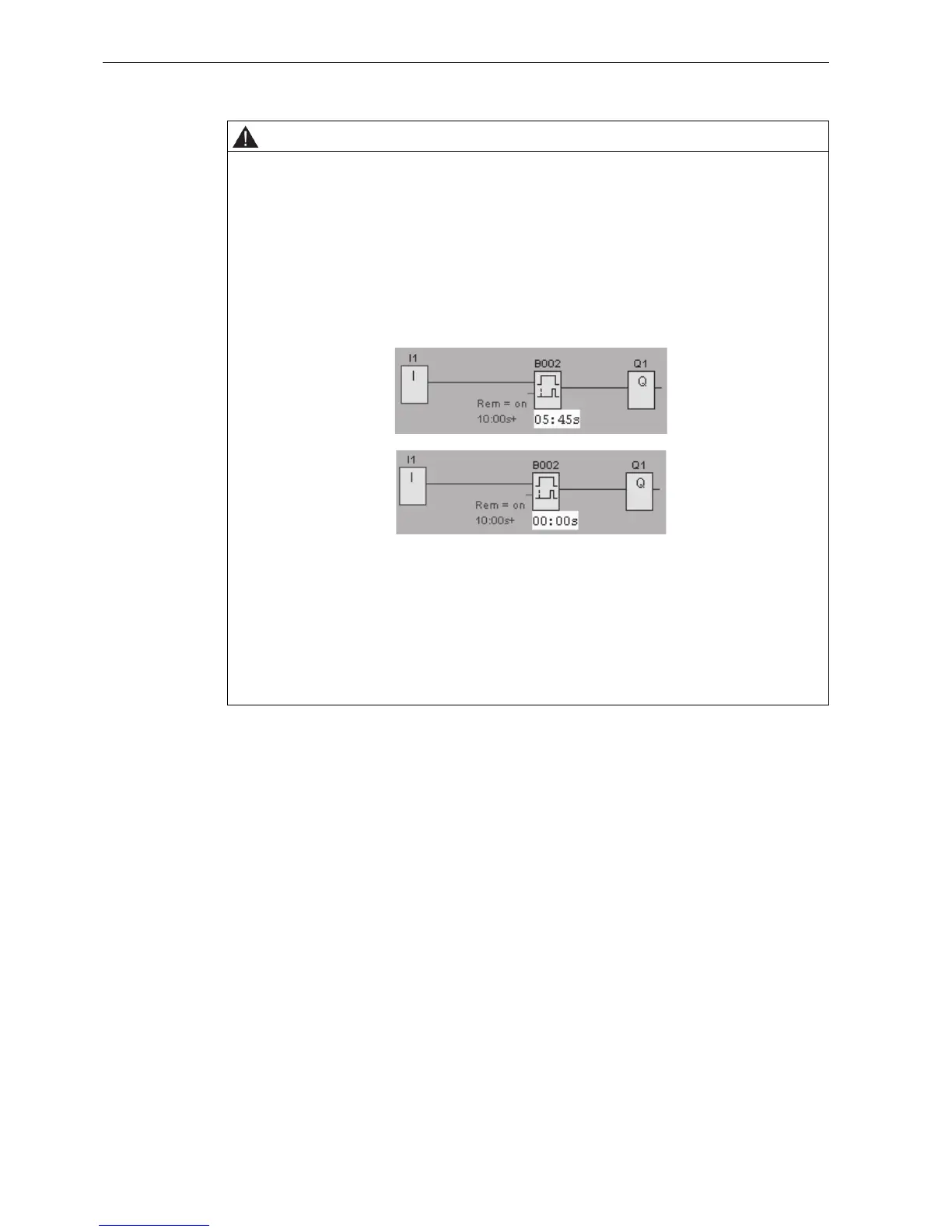
Example: On-delay
With an input (I1) connected to a Trg connector of an On-delay FB as shown in Fig.1, if I1 is
ON and the IDEC SmartRelay power is turned off and on, the timer current value of the On-
delay FB is sometimes reset as shown in Fig.2.
Other FBs are shown below.
• Function blocks whose timer current value is sometimes reset. Off-delay, On-delay, On-/Off-delay,
Retentive on-delay, Interval time-delay relay/Pulse output, Edge-triggered interval time-delay relay,
Operating hours counter, Asynchronous pulse generator, Stairwell Light Switch, Dual-function
switch, Stopwatch
• Function blocks whose output is sometimes set or reset when input (I*) is connected to a S(R)
connector with NOT.
Latching relay, Current impulse relay