Technical data
A.8 Technical data: FL1F-B12RCE/H12RCE, FL1F-M08B2R2
IDEC SmartRelay Manual
296
A.8 Technical data: FL1F-B12RCE/H12RCE, FL1F-M08B2R2
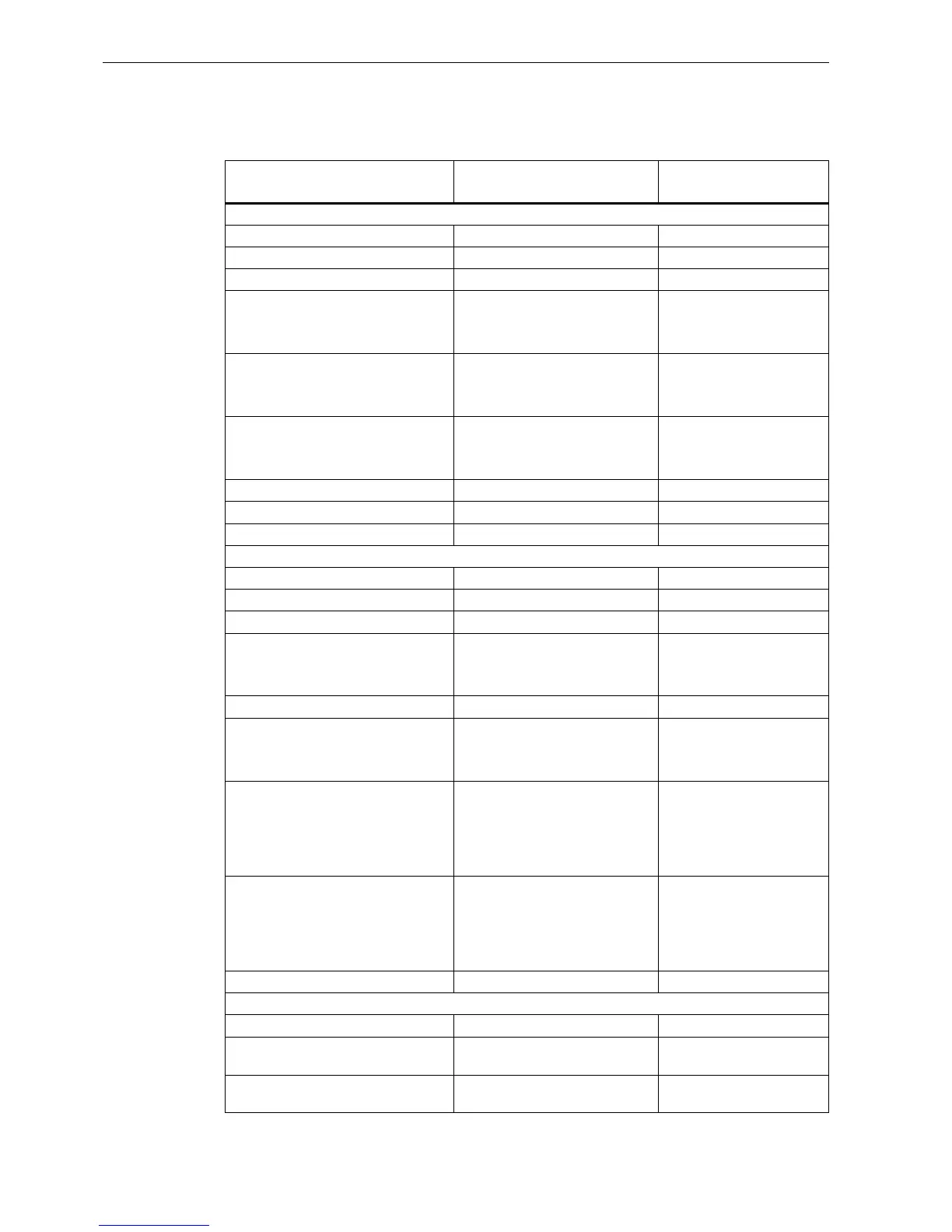
FL1F-B12RCE
FL1F-H12RCE
FL1F-M08B2R2
Power supply
Input voltage 12/24VDC 12/24VDC
Permissible range 10.8VDC to 28.8 VDC 10.8VDC to 28.8 VDC
Reverse polarity protection Yes Yes
Power consumption
• 12 VDC
• 24 VDC
• 30mA to 140 mA
• 15mA to 90 mA
• 10mA to 80 mA
• 10mA to 40 mA
Voltage failure buffering
• 12 VDC
• 24 VDC
• Typ. 2 ms
• Typ. 5 ms
• Typ. 2 ms
• Typ. 5 ms
Power loss
• 12 VDC
• 24 VDC
• 0.4W to 1.7 W
• 0.4W to 2.2 W
• 0.2W to 1.0 W
• 0.3W to 1.0 W
Backup of the real-time clock at 25°C Typ. 20 days - -
Accuracy of the real-time clock Typ. ± 2s/day - -
Electrical isolation No No
Digital inputs
Number 8 4
Electrical isolation No No
Number of high speed inputs 4 (I3, I4, I5, I6) 0
Input frequency
• Normal input
• High speed input
• Max. 4 Hz
• Max. 5 kHz
• Max. 4 Hz
• - -
Max. continuous permissible voltage 28.8 VDC 28.8 VDC
Input voltage L+
• Signal 0
• Signal 1
• < 5 VDC
• > 8.5 VDC
• < 5 VDC
• > 8.5 VDC
Input current at
• Signal 0
• Signal 1
< 0.88 mA (I3 to I6)
< 0.07 mA (I1, I2, I7, I8)
> 1.5 mA (I3 to I6)
> 0.12 mA (I1, I2, I7, I8)
< 0.88 mA
> 1.5 mA
Delay time at
• 0 to 1
• 1 to 0
• Typ. 1.5 ms
<1.0 ms (I3 to I6)
• Typ. 1.5 ms
<1.0 ms (I3 to I6)
• Typ. 1.5 ms
• Typ. 1.5 ms
Line length (unshielded) Max. 100 m Max. 100 m
Analog inputs
Number 4 (I1=AI3, I2=AI4, I7=AI1, I8=AI2) - -
Range 0VDC to 10 VDC
Input impedance 72 kΩ
- -
Cycle time for analog value
generation
300 ms - -