IDEC SmartRelay Manual
65
Programming IDEC SmartRelay
3.7 Writing and starting the circuit program
Wiring
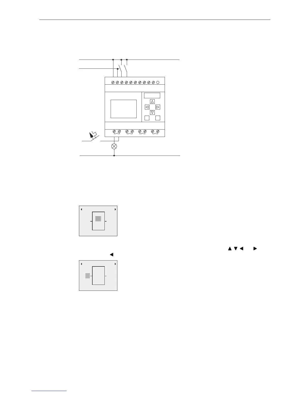
The corresponding wiring shows as follows:
S1 switches input I1, while S2 switches input I2. The load connects to the relay Q1.
3.7.3 Circuit program input
You can now write the circuit program, starting at the output and working towards the input.
IDEC SmartRelay initially shows the output:
You will see a solid square at Q1, which is the cursor. The cursor indicates your current
position in the circuit program. You can move the cursor by pressing the , , and keys.
Now press the key. The cursor moves to the left.
/ 1 , , , , , , , ,
4 4 4 4
/
1
6
6
/
1
4
,Q
4
7KHILUVW,'(&6PDUW5HOD\RXWSXW
4
4
,Q
7KHFXUVRULQGLFDWHV\RXUFXUUHQW
SRVLWLRQLQWKHFLUFXLWSURJUDP