IDEC SmartRelay Manual
43
IDEC SmartRelay installation and wiring
2.3 Wiring IDEC SmartRelay
2.3.5 Connecting the Ethernet interface
Base modules and text display are equipped with a 10/100 Mbit/s Ethernet RJ45 interface.
Requirements for the network cable
Use a shielded Ethernet cable to connect to the Ethernet interface. To minimize
electromagnetic interference, make sure you use a standard Category 5 shielded twisted-pair
Ethernet cable with a shielded RJ45 connector on each end.
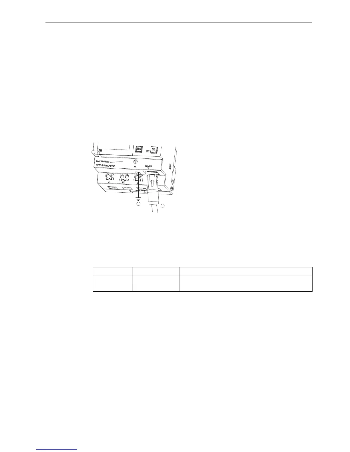
Connecting
You connect the FE terminal to earth ground, and connect a network cable to the Ethernet
interface.
Ethernet status LED
①
②
③
Earth ground
Ethernet cable, for connecting to the Ethernet interface
Ethernet status LED
LED type Color Description
Status LED Flashing orange IDEC SmartRelay is receiving/sending data across Ethernet.
Steady green IDEC SmartRelay is already connected to Ethernet.