EasyManuals Logo

IDEC SMARTRELAY User Manual

IDEC SMARTRELAY
338 pages
To Next Page IconTo Next Page
To Previous Page IconTo Previous Page
Page #67 background imageLoading...
Page #67 background image
IDEC SmartRelay Manual
55
Programming IDEC SmartRelay
3.3 From circuit diagram to IDEC SmartRelay program
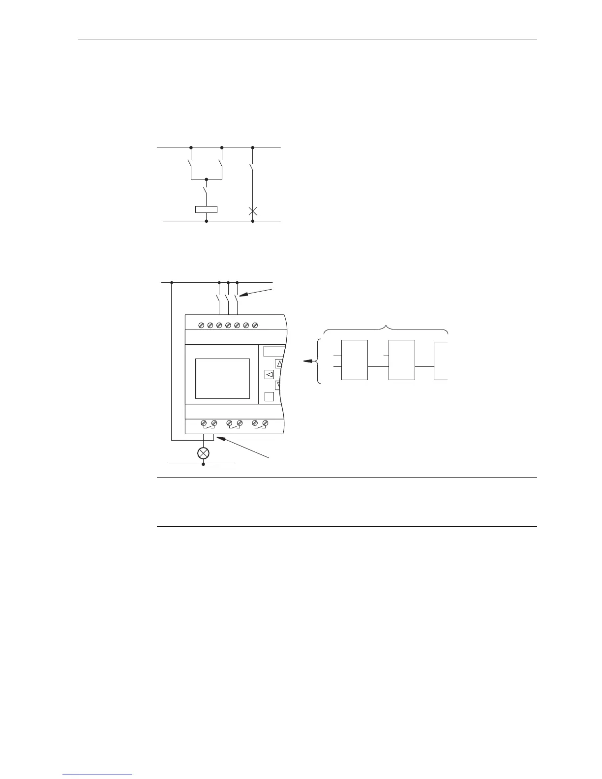
View of a circuit diagram
The following illustration shows a typical circuit diagram that represents the circuit logic:
Creating this circuit with IDEC SmartRelay
In IDEC SmartRelay you create a circuit logic by interconnecting blocks and connectors:
To create a new circuit logic in IDEC SmartRelay, start at the circuit output.
The output is the load or relay that is to be switched.
Convert the circuit logic into blocks by working through the circuit, starting at the output and
ending at the input:
Note
Although you have four inputs available for Basic functions list - GF (Page 116), most of the
views only show three inputs for reasons of clarity. You program this fourth input and assign
parameters just like you do with the other three inputs.
6
6
6
.
(
.
7KHVZLWFKHV6256$1'6
DFWLYDWHWKHUHOD\.DQGVZLWFK
RQWKHORDGDW(
/
1
66
,
,
,
4
ุ
/ 1 , , , ,
 
4 4 4
:LULQJRIWKHLQSXWV
&LUFXLWSURJUDPLQ,'(&6PDUW5HOD\
:LULQJRIWKHRXWSXWV
Phone: 800.894.0412 - Fax: 888.723.4773 - Web: www.clrwtr.com - Email: info@clrwtr.com

Table of Contents

Other manuals for IDEC SMARTRELAY

Questions and Answers:

Question and Answer IconNeed help?

Do you have a question about the IDEC SMARTRELAY and is the answer not in the manual?

IDEC SMARTRELAY Specifications

General IconGeneral
BrandIDEC
ModelSMARTRELAY
CategoryOther
LanguageEnglish

Related product manuals