Programming IDEC SmartRelay
3.3 From circuit diagram to IDEC SmartRelay program
IDEC SmartRelay Manual
56
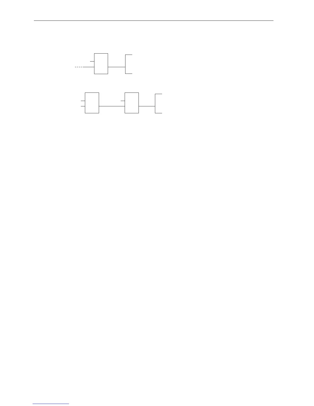
Step 1: Connect the normally open contact S3 in series with another circuit element to output
Q1. A series connection corrsponds to the AND block:
Step 2: Use an OR block to connect S1 and S2 in parallel. A parallel circuit corresponds to the
OR block:
Unused inputs
The circuit program automatically assigns the unused connectors a status that ensures
proper functioning of the relevant block.
In our example we shall use only two inputs of the OR block and two inputs of the AND block;
the third and fourth inputs are unused.
Now connect the I/O to IDEC SmartRelay.
Wiring
Connect the switches S1 to S3 to the screw terminals of your IDEC SmartRelay :
• S1 to connector I1 of IDEC SmartRelay
• S2 to connector I2 of IDEC SmartRelay
• S3 to connector I3 of IDEC SmartRelay
The output of the AND block controls the relay at output Q1. The load E1 connects to output Q1.
,
4