IDEC SmartRelay Manual
29
IDEC SmartRelay installation and wiring
2.3 iring IDEC SmartRelay
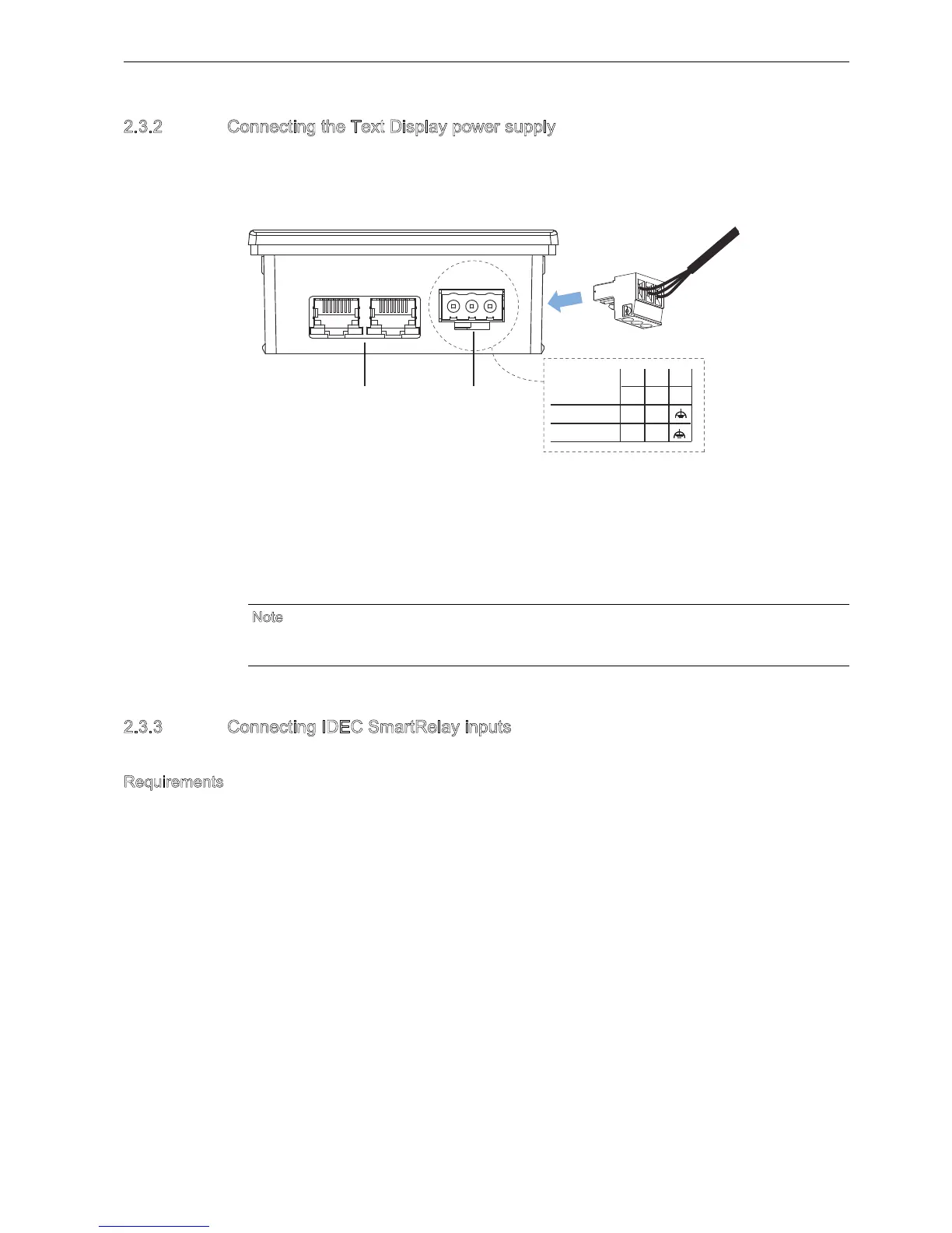
2.3.2 Connecting the Text Display power supply
ou must connect the FL1F-RD1 to an external power supply that supplies a voltage of
12VDC or 24VAC/VDC. Text Display includes a power connector. Connect the power supply
to the power connector then plug the power conncetor to the power supply interface on Text
Display.
2.3.3 Connecting IDEC SmartRelay inputs
Reuirements
At the inputs you connect sensor elements such as: momentary pushbuttons, switches, light
barriers, daylight control switches etc.
Ethernet interfaces
Power supply
The power connection is non-polar. If you connect a DC power supply to the Text
Display, you can connect the positive supply wire or negative supply wire to either
pin 1 or pin 2.
Pin 3 must be connected to the ground.
N
ote
IDEC recommends that you protect the Text Display with a 0.5 A safety fuse on the power
supply.
ཱ
9'&
9$&
3 3
/
/
)(
0
1