IDEC SmartRelay installation and wiring
2.3 Wiring IDEC SmartRelay
IDEC SmartRelay Manual
30
Sensor characteristics for IDEC SmartRelay
Sensor connections
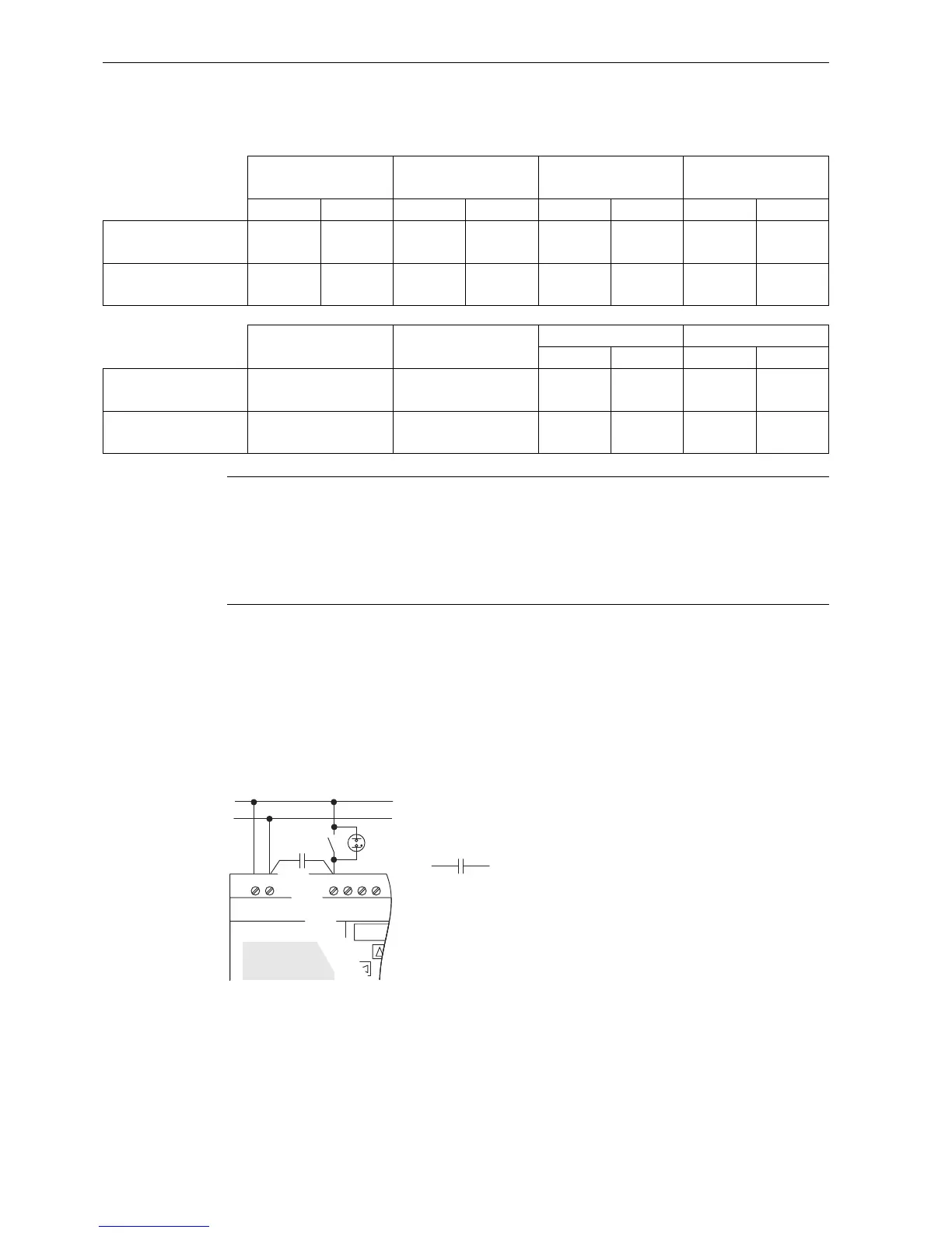
Connecting glow lamps and two-wire proximity switches (Bero) to FL1F-H12RCC/B12RCC or
FL1F-M08C2R2 (AC)
The figure below shows how you connect a switch with a glow lamp to IDEC SmartRelay. The
current that flows through the glow lamp allows IDEC SmartRelay to detect a "1" signal even
though the switch contact is not closed. If, however you use a switch that has the glow lamp
fitted with a power supply, this response does not occur.
FL1F-H12RCE
FL1F-B12RCE
FL1F-H12SCD
FL1F-H12RCA
FL1F-B12RCA
FL1F-H12RCC
FL1F-B12RCC
I3 ~ I6 I1,I2,I7,I8 I3 ~ I6 I1,I2,I7,I8 AC DC AC DC
Input voltage (Signal 0)
Input current (Signal 0)
< 5 V DC
< 0.88mA
< 5 V DC
< 0.07mA
< 5 V DC
< 0.9mA
< 5 V DC
< 0.07mA
< 5 V AC
< 1.2mA
< 5 V DC
< 1.2mA
< 40 V AC
< 0.05mA
< 30 V DC
< 0.06mA
Input voltage (Signal 1)
Input current (Signal 1)
>
8.5 V DC
> 1.5mA
>
8.5 V DC
> 0.12mA
> 12 V DC
> 2.1mA
> 12 V DC
> 0.18m
> 12 V AC
> 2.6mA
> 12 V DC
> 2.6mA
> 79 V AC
> 0.08 mA
> 79 V DC
> 0.13mA
FL1F-M08B2R2 FL1F-M08B1S2
FL1F-M08D2R2 FL1F-M08C2R2
AC DC AC DC
Input voltage (Signal 0)
Input current (Signal 0)
< 5 V DC
< 0.88mA
< 5 V DC
<0.88mA
< 5 V AC
< 1.1mA
< 5 V DC
< 1.1mA
< 40 V AC
< 0.05mA
< 30 V DC
< 0.06mA
Input voltage (Signal 1)
Input current (Signal 1)
> 8.5 V DC
> 1.5mA
> 12 V DC
> 2.1mA
> 12 V AC
> 2.63mA
> 12 V DC
> 2.63mA
> 79 V AC
> 0.08 mA
> 79 V DC
> 0.13mA
Note
FL1F-H12RCC/B12RCC contains two groups of four inputs, for a total of eight. Within each
group, you must operate all inputs on the same phase. Different phases are only possible
between the groups.
Example: I1 to I4 on phase L1, I5 to I8 on phase L2.
You must not connect the inputs of the FL1F-M08C2R2 to different phases.