Technical data
A.5 Technical data: FL1F-M08B1S2
IDEC SmartRelay Manual
290
1)
When you switch on FL1F-H12SCD or FL1F-M08B1S2, the CPU sends signal 1 to the digital outputs
for about 50 μs. Take this into account, especially when using devices that react to short pulses.
2)
The maximum switching rate is only dependent on the switching program's cycle time.
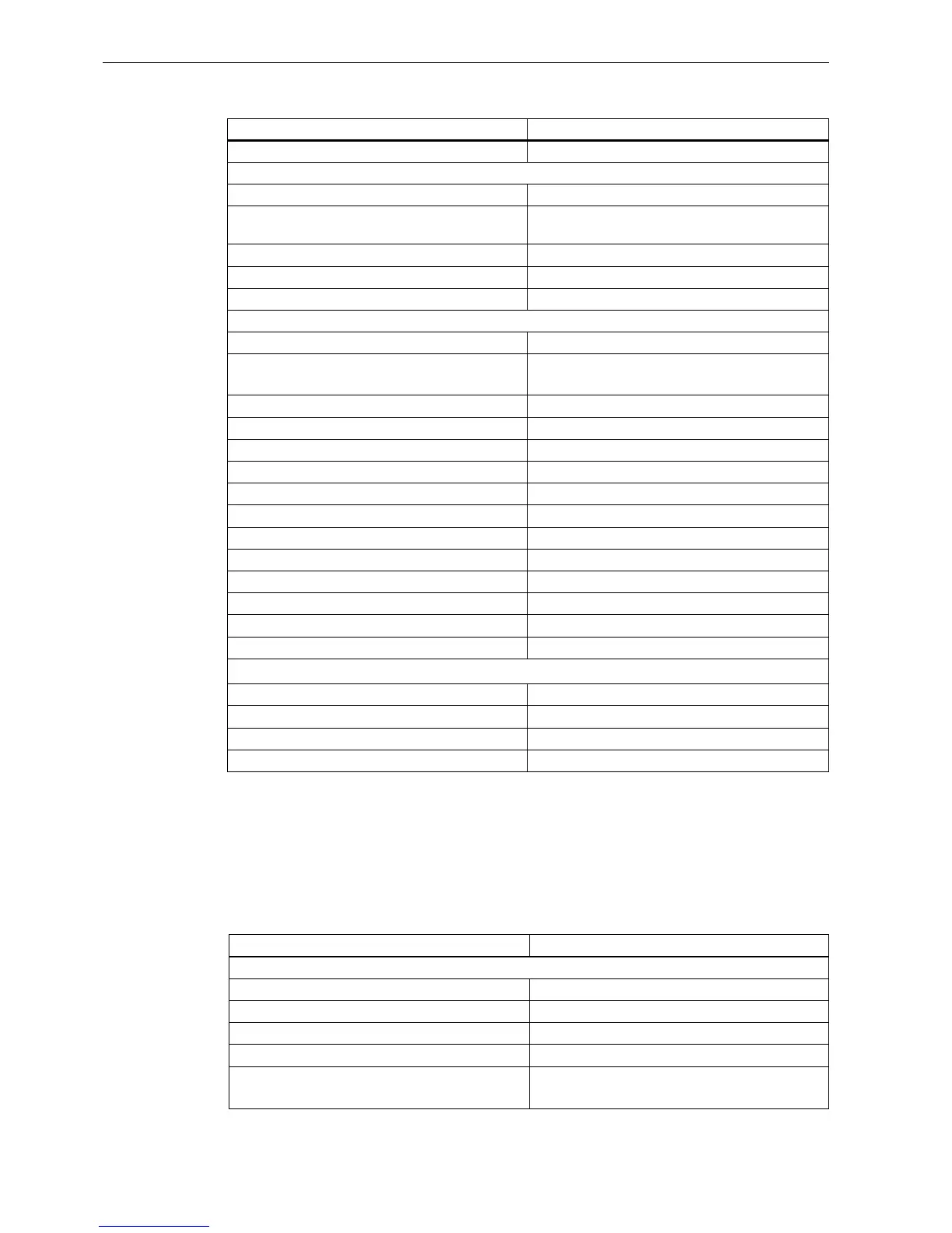
A.5 Technical data: FL1F-M08B1S2
Line length (unshielded) Max. 100 m
Analog inputs
Number 4 (I1=AI3, I2=AI4, I7=AI1, I8=AI2)
Range 0VDC to 10 VDC
Input impedance 72 kΩ
Cycle time for analog value generation 300 ms
Line length (shielded and twisted) Max. 10 m
Error limit ± 1.5% at FS
Digital outputs
Number 4
Output type Transistor,
current-sourcing
1)
Electrical isolation No
In groups of - -
Control of a digital input Yes
Output voltage ≤ Supply voltage
Output current Max. 0.3 A per channel
Short circuit-proof and overload-proof Yes
Short circuit current limitation Approx. 1 A per channel
Derating None; across the entire temperature range
Short circuit-proof cos 1 - -
Short circuit-proof cos 0.5 to 0.7 - -
Parallel output circuit for power increase Not permitted
Protection of output relay (if desired) - -
Switching rate
2)
Mechanical - -
Electrical 10 Hz
Ohmic load/lamp load 10 Hz
Inductive load 0.5 Hz
FL1F-M08B1S2
Power supply
Input voltage 24 VDC
Permissible range 20.4VDC to 28.8 VDC
Reverse polarity protection Yes
Permissible mains frequency - -
Power consumption from 24VDC 15mA to 40 mA (no load on digital output)
1.2 A (with max. load on digital output )
FL1F-H12SCD