IDEC SmartRelay Manual
291
Technical data
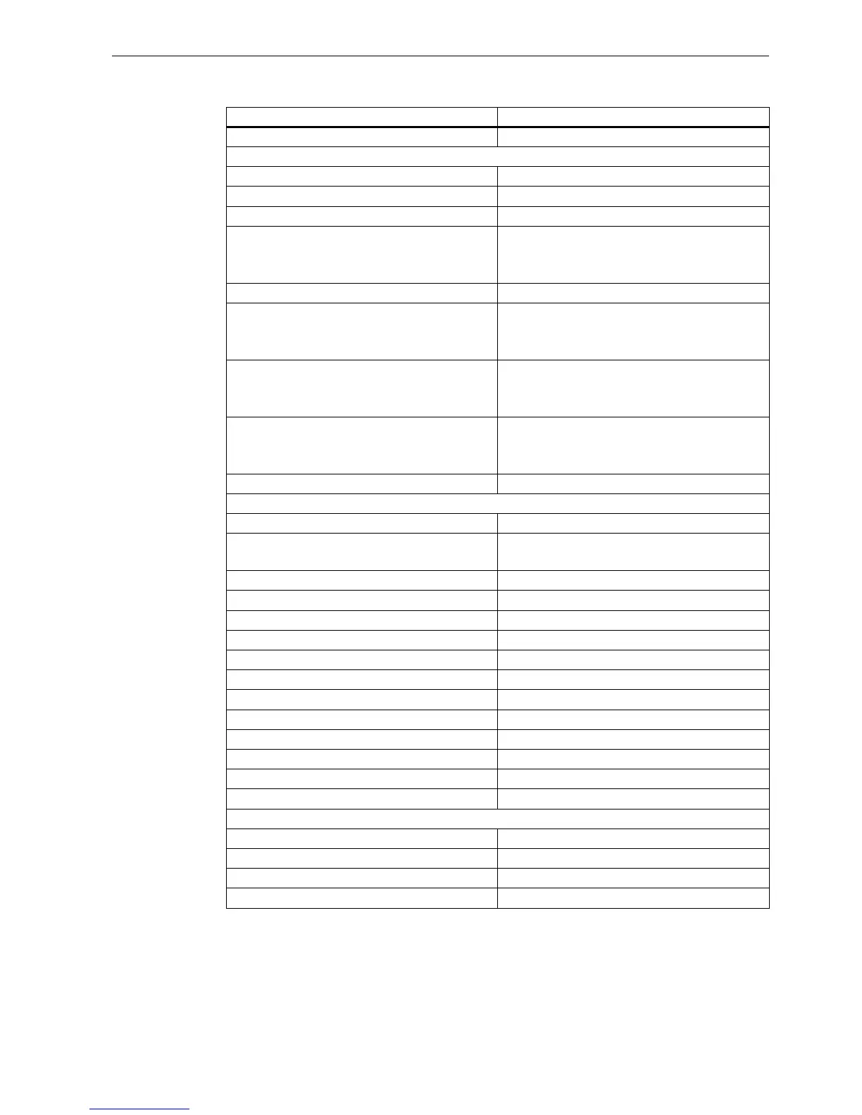
A.5 Technical data: FL1F-M08B1S2
1)
When you switch on FL1F-H12SCD or FL1F-M08B1S2, the CPU sends signal 1 to the digital outputs
for about 50 μs. Take this into account, especially when using devices that react to short pulses.
Power loss at 24 V 0.4W to 1.0 W
Digital inputs
Number 4
Electrical isolation No
Number of high speed inputs 0
Input frequency
• Normal input
• High speed input
• Max. 4 Hz
• - -
Max. continuous permissible voltage 28.8 VDC
Input voltage
• Signal 0
• Signal 1
L+
• < 5 VDC
• > 12 VDC
Input current at
• Signal 0
• Signal 1
• < 0.88 mA
• > 2.1 mA
Delay time at
• 0 to 1
• 1 to 0
• Typ. 1.5 ms
• Typ. 1.5ms
Line length (unshielded) Max. 100 m
Digital outputs
Number 4
Output type Transistor,
current-sourcing
1)
Electrical isolation No
In groups of - -
Control of a digital input Yes
Output voltage ≤ Supply voltage
Output current Max. 0.3 A per channel
Short circuit-proof and overload-proof Yes
Short circuit current limitation Approx. 1 A per channel
Derating None; across the entire temperature range
Short circuit-proof cos 1 - -
Short circuit-proof cos 0.5 to 0.7 - -
Parallel output circuit for power increase Not permitted
Protection of output relay (if desired) - -
Switching rate
Mechanical - -
Electrical 10 Hz
Ohmic load/lamp load 10 Hz
Inductive load 0.5 Hz
FL1F-M08B1S2