B
IDEC SmartRelay Manual
303
Determining the cycle time
The program cycle is the complete execution of the circuit program, that is, primarily the
reading in of the inputs, the processing of the circuit program and the subseuent writing the
outputs. The cycle time is the time reuired to execute a circuit program once in full.
ou can determine the time reuired for a program cycle using a short test program. Create
this test program in IDEC SmartRelay to return a value from which you can calculate the cycle
time.
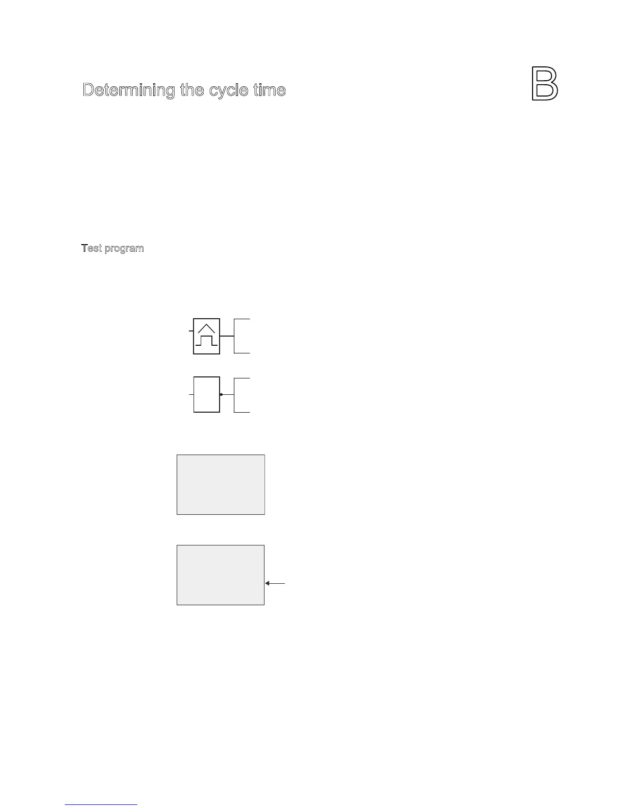
Test program
To program this test program, follow these steps:
1. Create the test program by linking an output to a freuency trigger and connecting the
trigger input with an inverted marker.
2. Configure the freuency trigger as shown below. IDEC SmartRelay generates a pulse in
each program cycle due to the inverted marker. The trigger interval is 2 seconds.
3. Now start the circuit program and switch IDEC SmartRelay to parameter assignment
mode. In this mode, view the trigger parameters.
4. The reciprocal value of f
a
is euivalent to the IDEC SmartRelay execution time of the
current circuit program in its memory.
1/f
a
cycle time in s
2XWSXW4[RU
RWKHUIODJ0[