IDEC SmartRelay Manual
221
IDEC SmartRelay functions
4.4 Special functions list - SF
4.4.31 Pulse width modulator (PM)
Short description
The Pulse idth Modulator (PM) instruction modulates the analog input value Ax to a
pulsed digital output signal. The pulse width is proportional to the analog value Ax.
Parameter T
Note the defaults of the T parameters listed in topic Time response (Page 124).
The periodic time T can be provided by the actual value of another already-programmed
function. ou can use the actual value of the following functions:
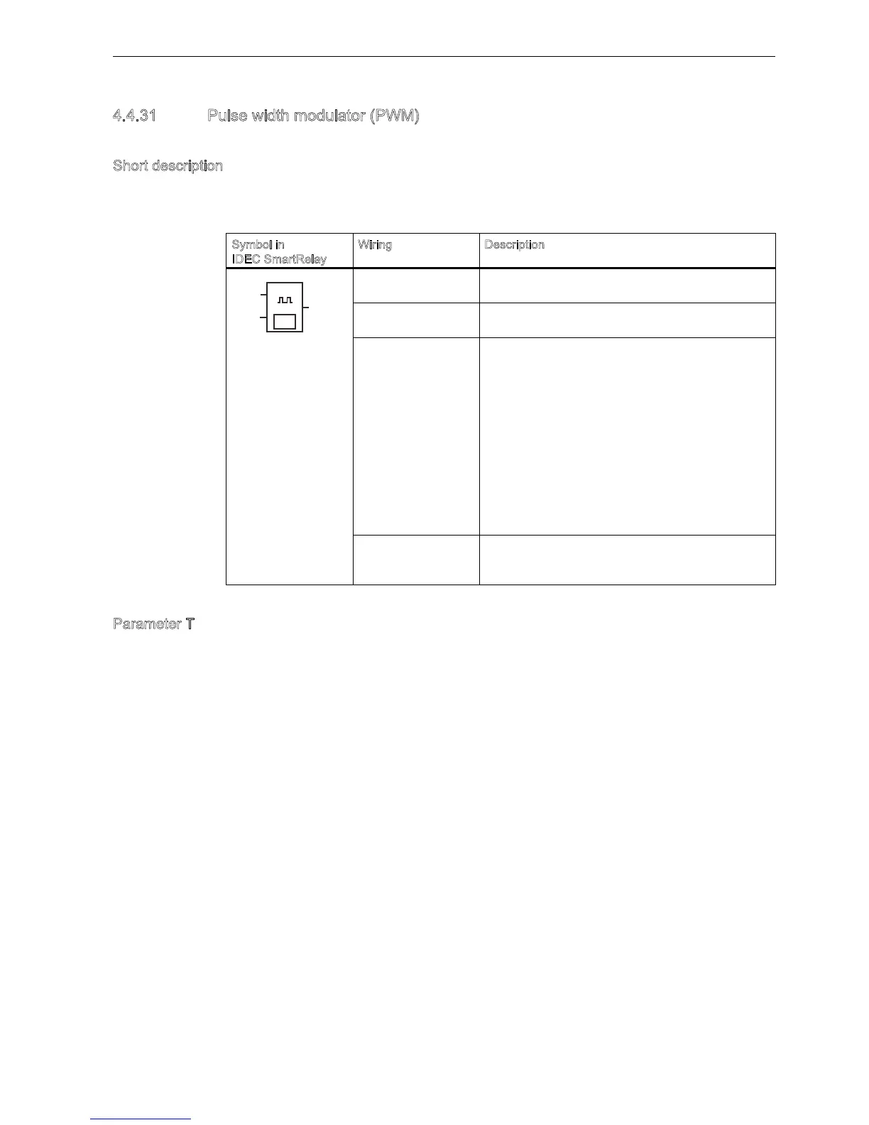
Symbol in
IDEC SmartRelay
iring Description
Input En A positive edge (0 to 1 transition) at input En enables
the PM function block.
Input Ax Analog signal to be modulated to a pulsed digital
output signal.
Parameter A: gain
Range of values: -10.00 to 10.00
B: zero offset
Range of values: 10,000 to 10,000
T: periodic time over which the digital output is
modulated
p: number of decimals
Range of values: 0, 1, 2, 3
Min:
Range of values: -20,000 to 20,000
Max:
Range of values: -20,000 to 20,000
Output is set or reset for the proportion of each time period
according to the proportion of the standardized value
Ax to the analog value range.
aᇄ
4
(Q
3DU
$[