IDEC SmartRelay functions
4.4 Special functions list - SF
IDEC SmartRelay Manual
186
Example
In a heating control system, the supply T
v
and return line temperatures T
r
are to be
compared, for example with a sensor at AI2.
A control signal is to be triggered (for example heater On) when the difference between the
supply and return line temperatures is greater than 15 C. The control signal is reset when the
difference is less than 5 C.
The process variable of the temperature is to be shown in parameter assignment mode.
The thermocouples available have the following technical data: -30 C to 70 C, 0 VDC to 10
VDC.
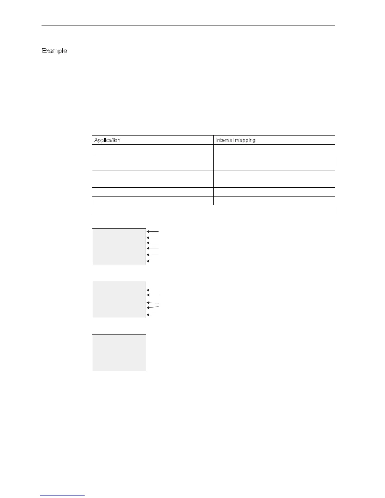
Configuration (example):
View in parameter assignment mode (example):
View in the message text (example):
Application Internal mapping
-30 C to 70 C 0 VDC to 10 VDC 0 to 1000
0 C 300
Offset -30
Range of values:
-30 C to 70 C 100
1000
Gain 100/1000 0.1
On threshold 15 C Threshold 15
Off threshold 5 C Threshold 5
See also topic Calculating the gain and offset of analog values (Page 126).