IDEC SmartRelay functions
4.4 Special functions list - SF
IDEC SmartRelay Manual
208
Functional description
The function reads the value at input In with a positive edge (0 to 1 transition) at input Trg (Trigger).
This value is applied to shift register bit Sx.1 or Sx.8 depending on the shifting direction,
where "x" refers to the index number of the shift register and the number after the decimal
point refers to the bit number:
• Shift up: the value at input In is set at Sx.1; the previous value at Sx.1 is shifted to Sx.2;
the previous value at Sx.2 is shifted to Sx.3 etc.
• Shift down: the value at input In is set at Sx.8; the previous value at Sx.8 is shifted to Sx.7;
the previous value at Sx.7 is shifted to Sx.6 etc.
Output Q returns the value of the configured shift register bit.
If retentivity is disabled, the shift function restarts at Sx.1 or Sx.8 after a power failure. When
enabled, retentivity always applies to all shift register bits.
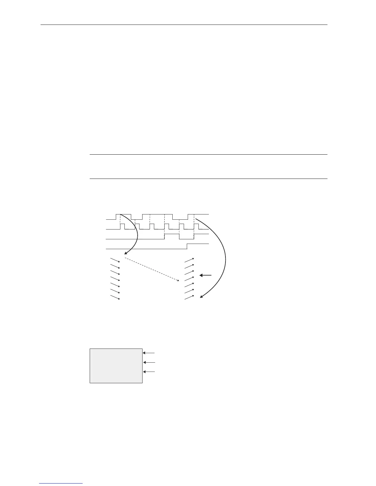
Timing diagram
The timing diagram example for the shift register in IDEC SmartRelay is shown as follows:
Setting the Par parameter
View in programming mode (example):
The view above indicates that the configured shift register bit is S4.8.
This special function is not available in parameter assignment mode.
Note
There are a maximum of four shift register function blocks available for use in the circuit
program in IDEC SmartRelay.