IDEC SmartRelay Manual
223
IDEC SmartRelay functions
4.4 Special functions list - SF
Examples with timing diagrams
The following examples show how the PWM instruction modulates a digital output signal from
the analog input value:
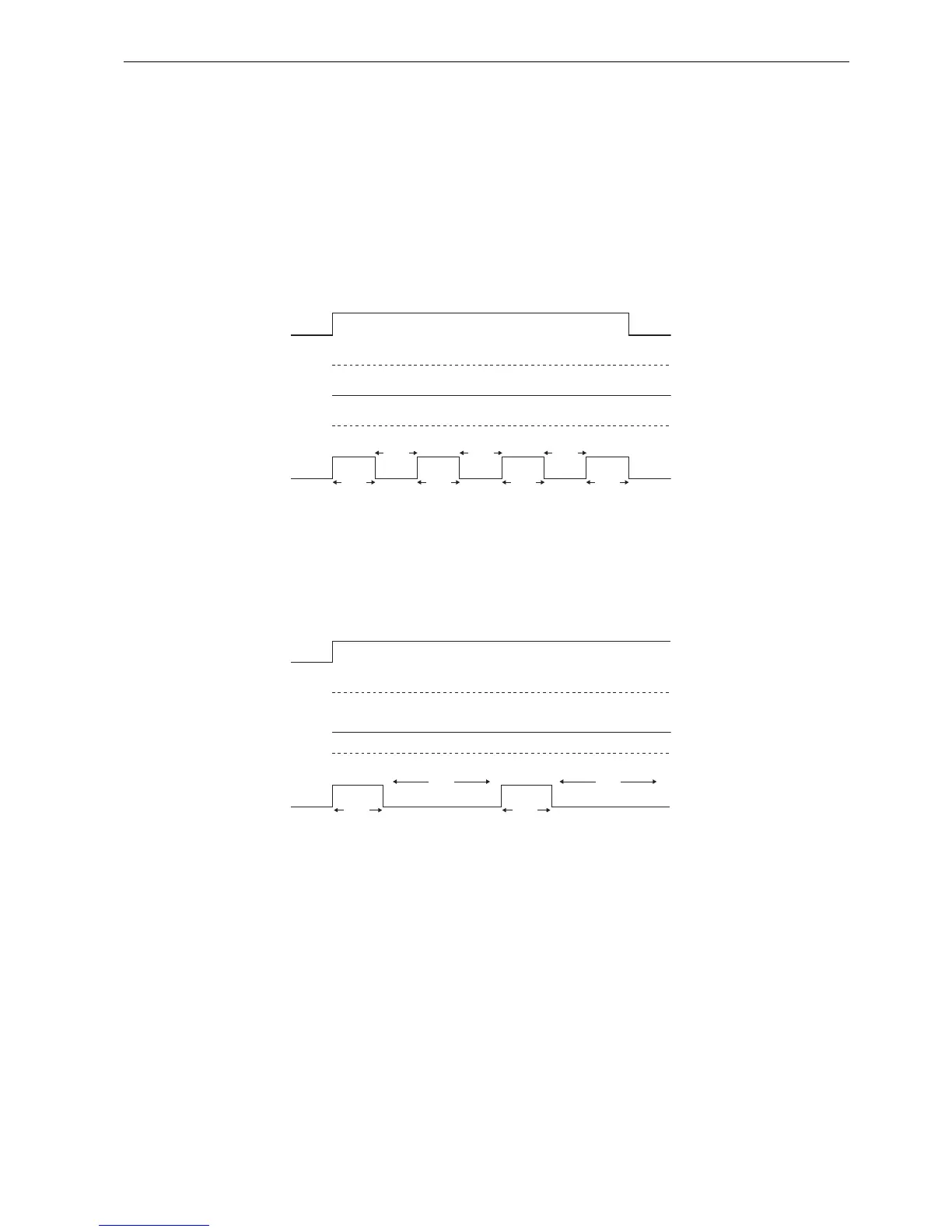
Example 1
Analog input value: 500 (range 0 to 1,000)
Periodic time T: four seconds
The digital output of the PWM function is 2 seconds high, 2 seconds low, 2 seconds high, 2
seconds low and continues in that pattern as long as parameter "En" = high.
Example 2
Analog input value: 300 (range 0 to 1,000)
Periodic time T: 10 seconds
The digital output of the PWM function is three seconds high, seven seconds low, three
seconds high, seven seconds low and continues in that pattern as long as parameter "En" =
high.
Calculation rule
Q = 1, for (Ax - Min)/ (Max - Min) of time period T, when Min < Ax < Max.
Q = 0, for PT - [ (Ax - Min) / (Max - Min) ] of periodic time T.
Note: Ax in this calculation refers to the actual value Ax as calculated using the Gain and
Offset.