EasyManuals Logo

IDEC SMARTRELAY User Manual

IDEC SMARTRELAY
338 pages
To Next Page IconTo Next Page
To Previous Page IconTo Previous Page
Page #28 background imageLoading...
Page #28 background image
IDEC SmartRelay installation and wiring
2.1 Modular IDEC SmartRelay setup
IDEC SmartRelay Manual
16
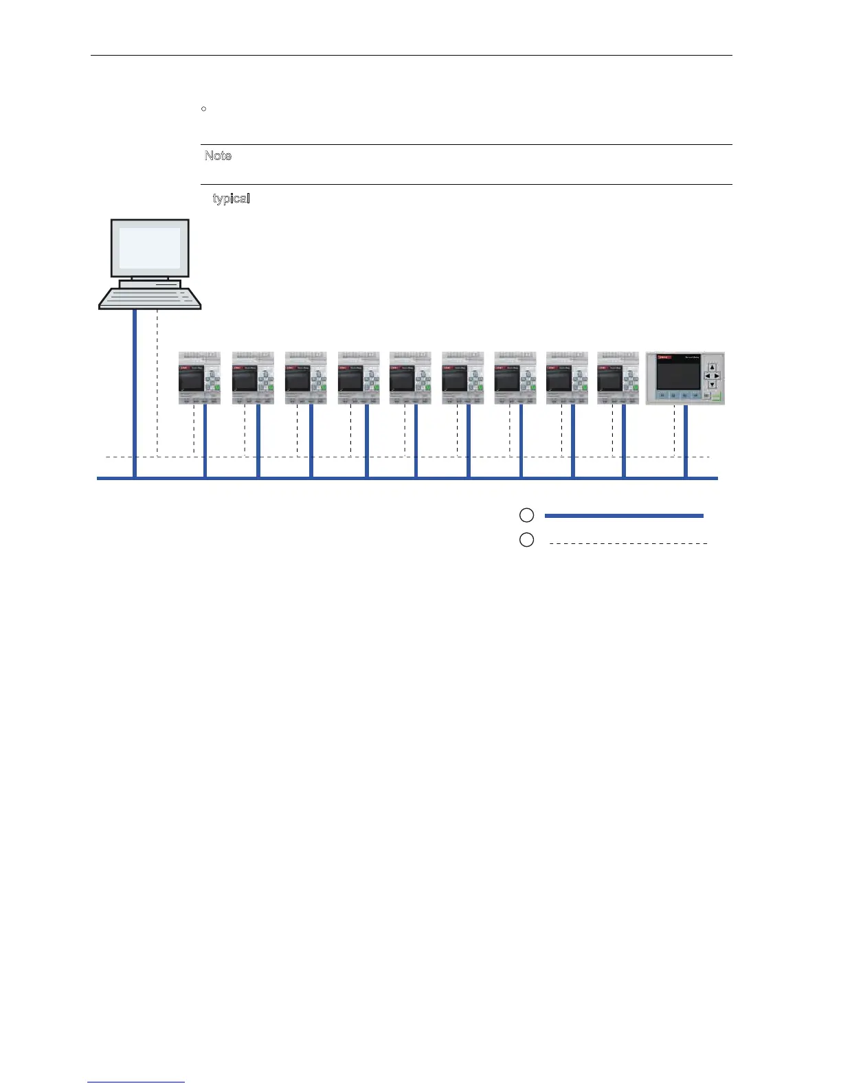
A maximum of one TCP/IP Ethernet connection between a Base Module and a PC with
indLGC V8.0 installed.
A typical IDEC SmartRelay network setup is shown below:
N
ote
ou can only construct an IDEC SmartRelay network using indLGC V8.0.
Physical Ethernet connections
Logical connection for communication between IDEC SmartRelay and PC (by TCP/IP-based Ethernet)
)/) )/) )/) )/) )/) )/)5'
:LQG/*&
9
)/)
)/))/)
)/)
Phone: 800.894.0412 - Fax: 888.723.4773 - Web: www.clrwtr.com - Email: info@clrwtr.com

Table of Contents

Other manuals for IDEC SMARTRELAY

Questions and Answers:

Question and Answer IconNeed help?

Do you have a question about the IDEC SMARTRELAY and is the answer not in the manual?

IDEC SMARTRELAY Specifications

General IconGeneral
BrandIDEC
ModelSMARTRELAY
CategoryOther
LanguageEnglish

Related product manuals