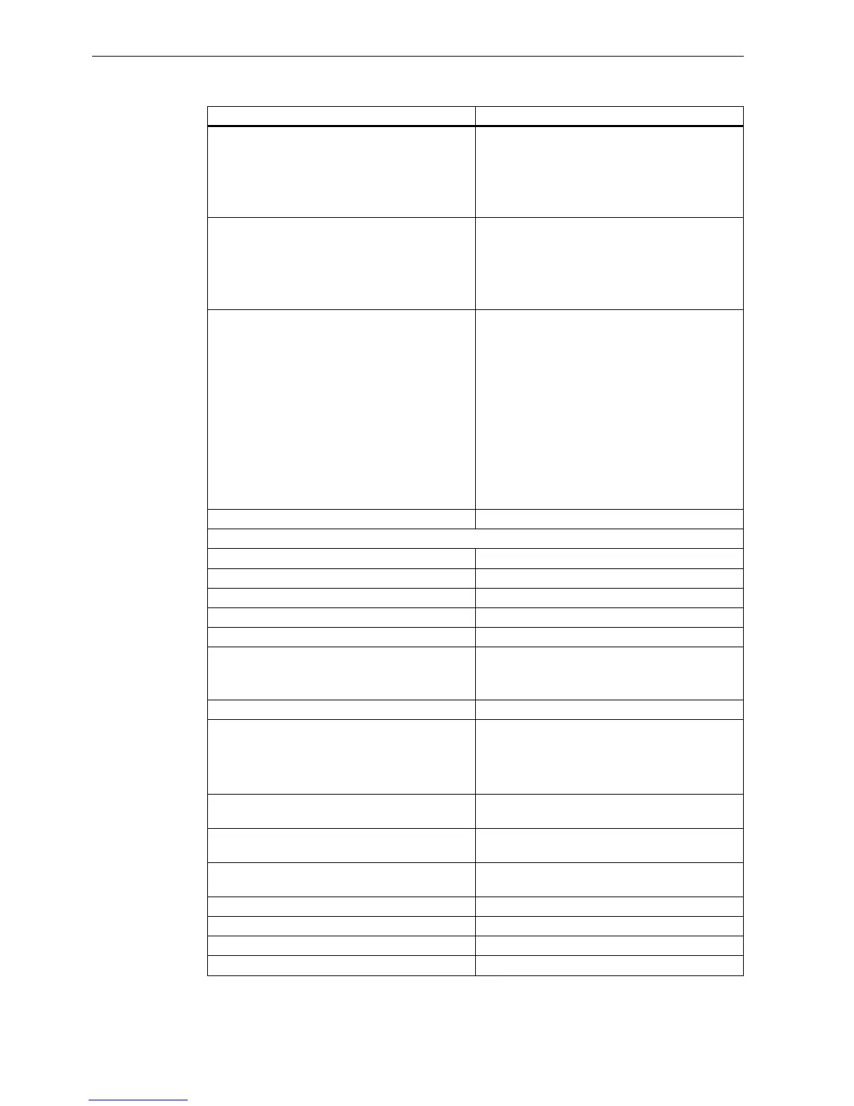
Technical data
A.3 Technical data: FL1F-M08C2R2
IDEC SmartRelay Manual
288
Input voltage L1
• Signal 0
• Signal 1
• Signal 0
• Signal 1
• < 40 VAC
• > 79 VAC
• < 30 VDC
• > 79 VDC
Input current at
• Signal 0
• Signal 1
• Signal 0
• Signal 1
• < 0.05 mA AC
• > 0.08 mA AC
• < 0.06 mA DC
• > 0.13 mA DC
Delay time at 0 to 1:
• 120 VAC
• 240 VAC
• 120 VDC
• 240 VDC
Delay time at 1 to 0:
• 120 VAC
• 240 VAC
• 120 VDC
• 240 VDC
• Typ. 40ms
• Typ. 30 ms
• Typ. 25 ms
• Typ. 20 ms
• Typ. 45ms
• Typ. 70 ms
• Typ. 60 ms
• Typ. 75 ms
Line length (unshielded) Max. 100 m
Digital outputs
Number 4
Output type Relay outputs
Electrical isolation Yes
In groups of 1
Control of a digital input Yes
Continuous current I
th
Recommended range of application ≥ 100mA at
12VAC/VDC
Max. 5 A per relay
Surge current Max. 30 A
Incandescent lamp load (25000 switching cycles)
at:
230/240VAC
100/120VAC
1000W
500W
Fluorescent tubes with ballast (25000 switching
cycles)
10 x 58 W (at 230/240VAC)
Fluorescent tubes, conventionally compensated
(25000 switching cycles)
1 x 58 W (at 230/240VAC)
Fluorescent tubes, uncompensated (25000
switching cycles)
10 x 58 W (at 230/240VAC)
Short circuit-proof cos 1 Power protection B16, 600 A
Short circuit-proof cos 0.5 to 0.7 Power protection B16, 900 A
Derating None; across the entire temperature range
Parallel output circuits for power increase Not permitted
FL1F-M08C2R2