IDEC SmartRelay Manual
293
Technical data
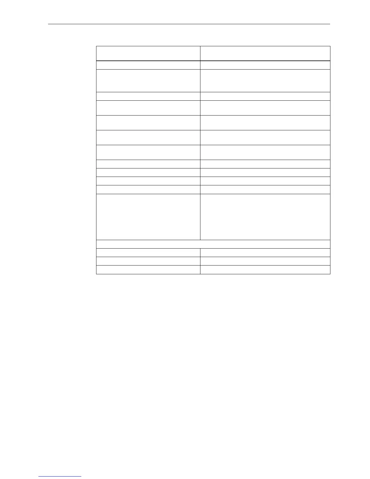
A.6 Technical data: FL1F-H12RCA/B12RCA
Notice: For fluorescent lamps with capacitors, you must consider the technical data of
fluorescent lamp ballasts. If the current exceeds the maximum allowed surge current,
appropriate contactor relays must switch the flourescent lamps.
Control of a digital input Yes
Continuous current I
th
Recommended range of application ≥ 100mA at
12VAC/VDC
Max. 10 A per relay
Surge current Max. 30 A
Incandescent lamp load
(25000 switching cycles) at
1000 W
Fluorescent tubes with ballast
(25000 switching cycles)
10 x 58 W
Fluorescent tubes, conventionally
compensated (25000 switching cycles)
1 x 58 W
Fluorescent tubes, uncompensated
(25000 switching cycles)
10 x 58 W
Derating None; across the entire temperature range
Short circuit-proof cos 1 Power protection B16, 600 A
Short circuit-proof cos 0.5 to 0.7 Power protection B16, 900 A
Parallel output circuits for power increase Not permitted
Protection of output relay
(if desired)
Max. 16 A,
characteristic B16
Switching rate
Mechanical 10 Hz
Ohmic load/lamp load 2 Hz
Inductive load 0.5 Hz
FL1F-H12RCA
FL1F-B12RCA