IDEC SmartRelay Manual
33
IDEC SmartRelay installation and wiring
2.3 iring IDEC SmartRelay
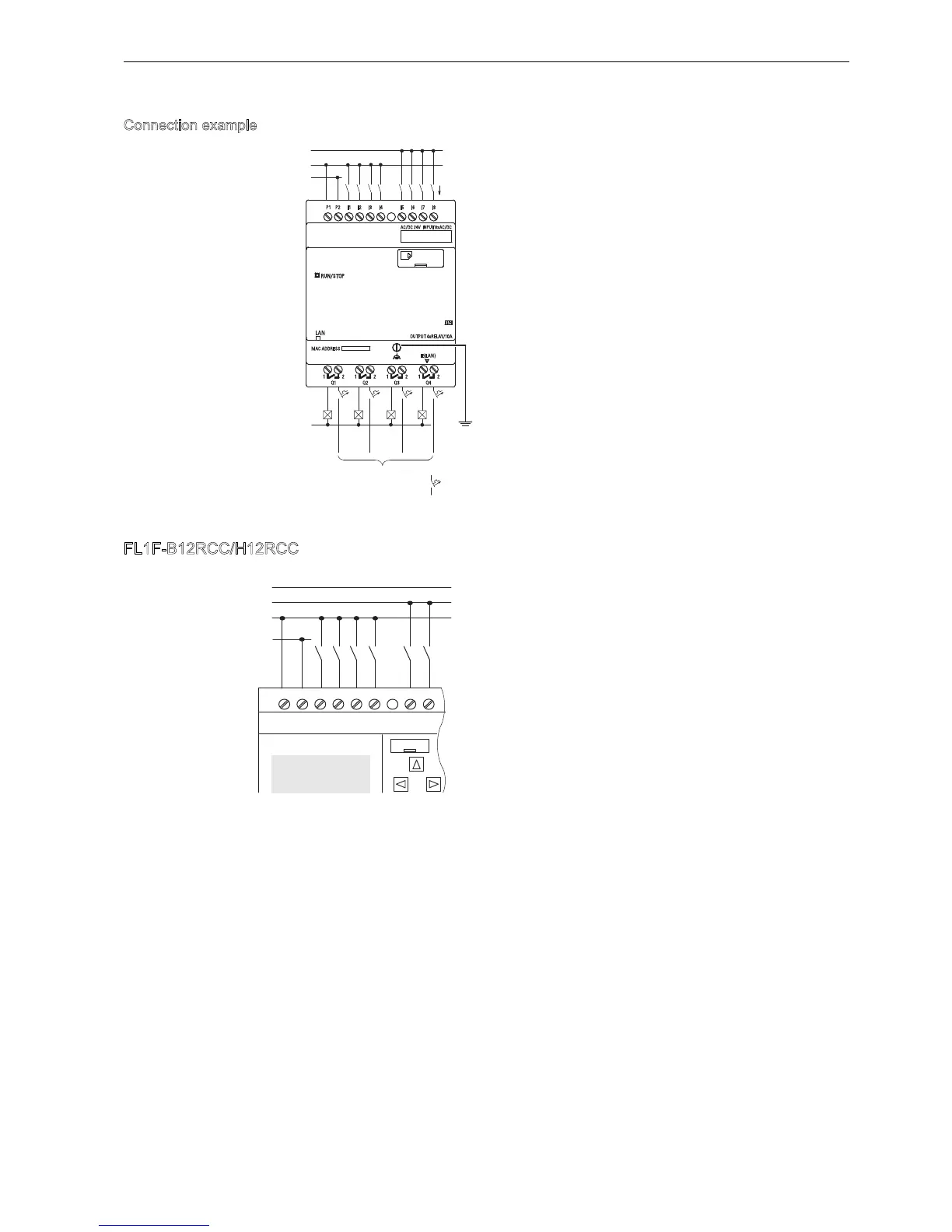
Connection example
FL1F-B12RCC/H12RCC
The inputs of these devices are in two
groups, each consisting of four inputs.
Different phases are only possible between
groups, but not within the groups.
1
09
1
9$&9'&
/