EasyManuals Logo

IDEC SMARTRELAY User Manual

IDEC SMARTRELAY
338 pages
To Next Page IconTo Next Page
To Previous Page IconTo Previous Page
Page #52 background imageLoading...
Page #52 background image
IDEC SmartRelay installation and wiring
2.3 iring IDEC SmartRelay
IDEC SmartRelay Manual
40
IDEC SmartRelay with transistor outputs
ou can identify IDEC SmartRelay versions with transistor outputs by the fact that the letter R is
missing from their type name. The outputs are short circuit-proof and overload-proof. An auxiliary
load voltage supply is not necessary, because IDEC SmartRelay supplies the load voltage.
Reuirements for transistor outputs
The load connected to IDEC SmartRelay must have the following characteristics:
The maximum switched current is 0.3 A per output.
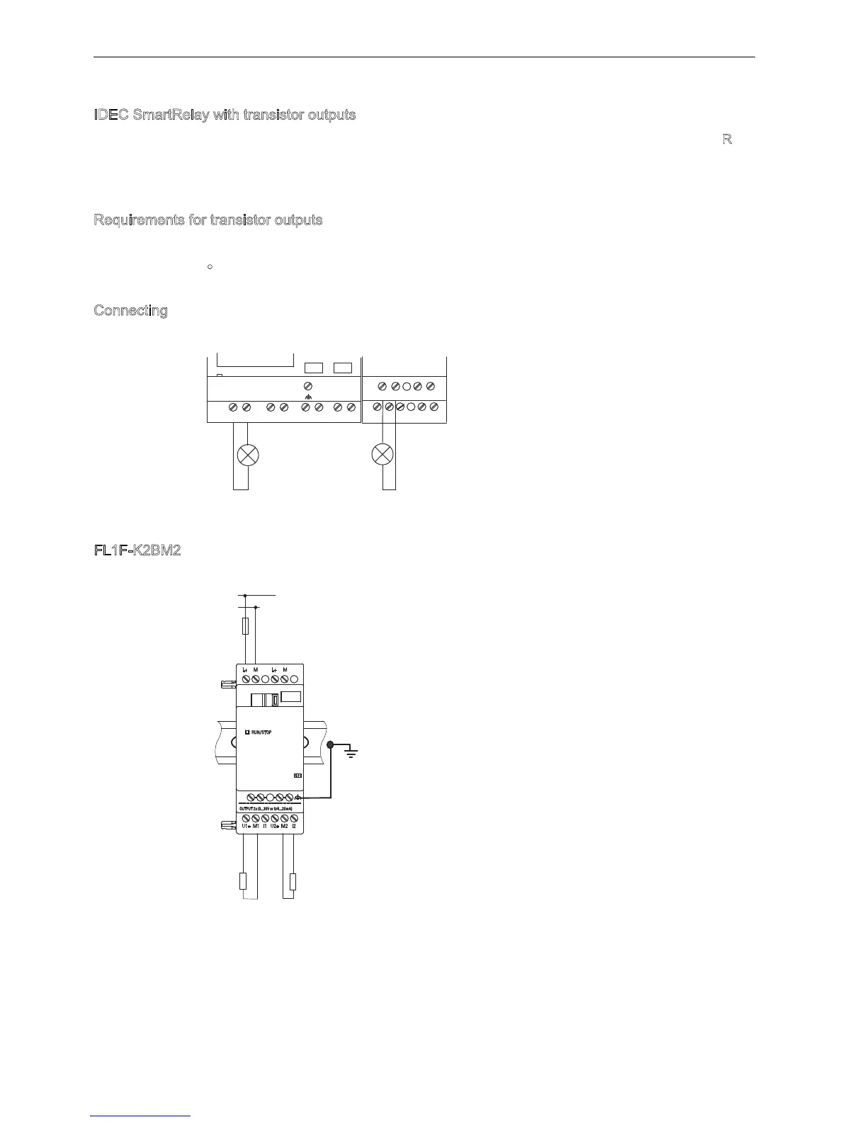
Connecting
Connect the load to an IDEC SmartRelay with transistor outputs as shown below:
FL1F-2BM2
The illustration below shows an example of how to connect the voltage or current load.
Earth
Standard DIN rail
4 0 4 0
4 0 4 0
/RDG9'&$PD[
/RDG
/RDG
V1, V2: 0 ... 10 VDC
R1: >= 5 kΩ
I1, I2: 0/4 ... 20 mA
R2: <= 250 Ω
0
/
R2
0 ... 10 V
0/4 ... 20 mA
R1
L+
U1+ M1 M2 I2I1 U2+
'&9
M L+ M
Phone: 800.894.0412 - Fax: 888.723.4773 - Web: www.clrwtr.com - Email: info@clrwtr.com

Table of Contents

Other manuals for IDEC SMARTRELAY

Questions and Answers:

Question and Answer IconNeed help?

Do you have a question about the IDEC SMARTRELAY and is the answer not in the manual?

IDEC SMARTRELAY Specifications

General IconGeneral
BrandIDEC
ModelSMARTRELAY
CategoryOther
LanguageEnglish

Related product manuals