Page: 4
JFS-A1 INSTALLATION, OPERATION, AND INSTRUCTION MANUAL
Document #: DOC230
Issued: August 27, 2012
Revised: N/A
SECTION 2: BEFORE YOU START INSTALLATION
is section addresses information that will help you in completing a successful installation, such as the JFS-A1
cabinet layout, specications, environmental considerations, and calculating the battery circuit and SLC current
draw requirements.
SystemSpecications
Cabinet Description
y Sixteen (16) gauge sheet steel with hinged, removable locked door
y Enclosure dimensions – 16" x 17" x 3-7/8"
Visual Indicators
y LCD (2 x 16 alphanumeric character display)
y LED indicators (Red, Green, Amber)
LCD Description
y Alarm, Supervisory and Trouble conditions display applicable condition, status and circuit for each correlating
condition
EnvironmentalSpecications
y Mount indoors only.
y Temperature 32° to 120°F, humidity 93% non-condensing.
y Verify panel is properly grounded.
y Remove all electronic assemblies prior to any drilling, ling, reaming, or punching of the enclosure. When
possible, make all cable entries from the sides, bottom, or rear of the cabinet. Verify that they will not interfere
with the batteries or other components.
y e panel and system must be tested and maintained in accordance with all local and national codes and
ordinances.
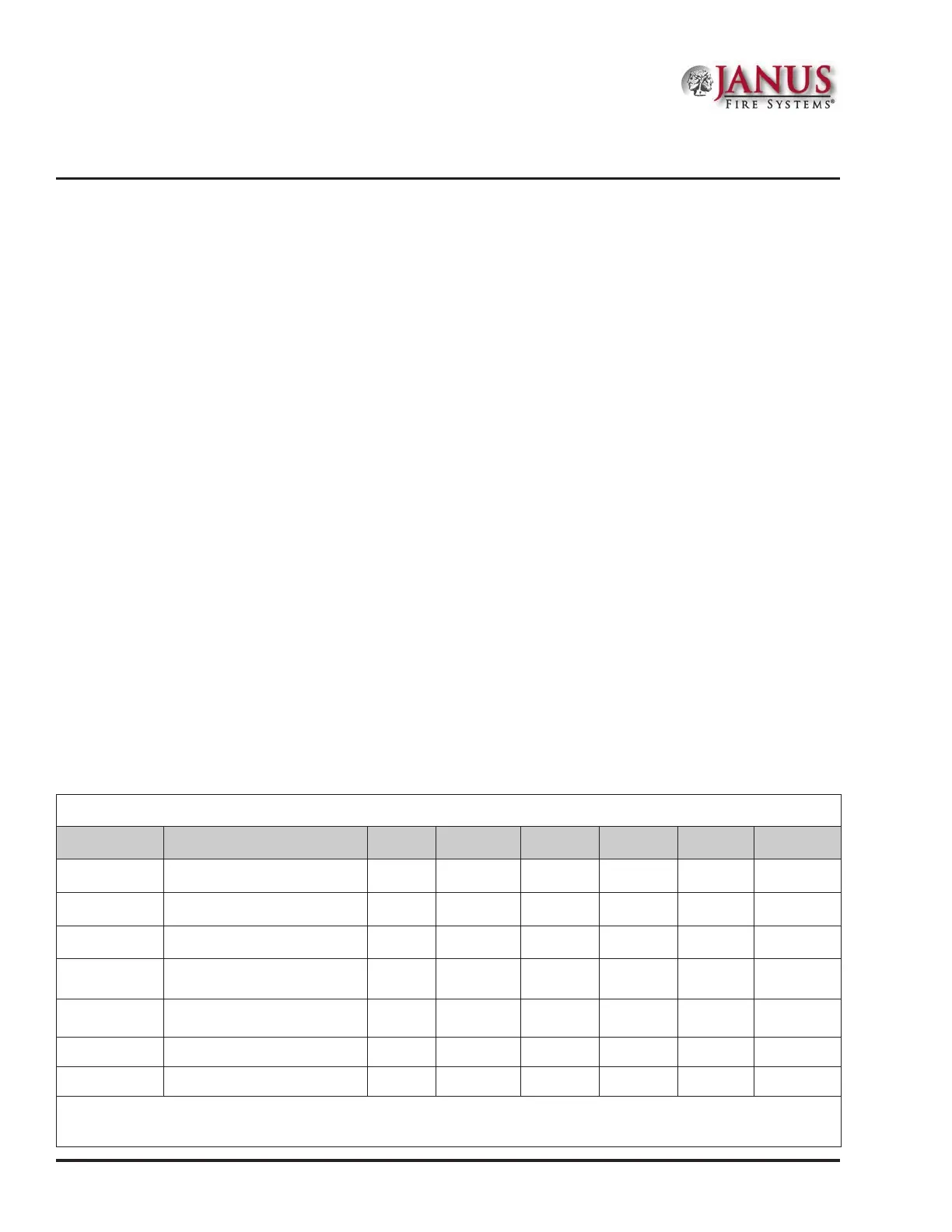
SystemCongurations/Appliances
Table 2: SystemCongurations/Appliances
Model Description Local
Releasing
Service
Auxiliary
Remote
Station
Central
Station
Proprietary
JFS-A1 Main Board/Panel Assembly Y Y Y Y Y Y
CA-6075 Class A Expander O O O O O O
UD-1000 DACT N N N Y Y Y
RA-6500R
or RA-6075R
LCD type remote Annunciator O O O O O O
PSN-1000 or
PSN-1000(E)
Intelligent Power Supply
Expander
O O O O O O
3005013 End of line resistor assembly Y Y Y Y Y Y
3005012 End of line resistor and diode N Y Y N N N
Y = Yes, required for applicable section
N = No, not required for applicable section
O = Optional, may or may not be used, has no affect on the applicable section.

 Loading...