Page: 32
JFS-A1 INSTALLATION, OPERATION, AND INSTRUCTION MANUAL
Document #: DOC230
Issued: August 27, 2012
Revised: N/A
Installing the DACT
Phone lines are high voltage and should be run in a separate conduit from other circuits. e wire conductors connecting
the DACT to the phone system should be 26 AWG or larger.
e UD-1000 Digital Alarm Communicator Transmitter provides connections for two (2) phone lines for
communication to a monitoring station. e UD-1000 DACT communicates using the SIA-DCS or Ademco
Contact ID protocols. Only one UD-1000 is allowed per main control panel, for convenience the UD-1000 is
typically programmed as device ID #01.
e UD-1000 must be installed prior to any other telephone equipment in the building to ensure proper operation. An RJ31X
jack can be installed to provide the connection to the telephone lines, a patch cable between the RJ31X jack and the built in
RJ-11 jacks on the UD-1000 provide a convenient connection method. e UD-1000 automatically monitors
each phone line for voltage and has the ability to seize the line and connect with a remote receiver. Once the
communication is complete, the DACT will hang up the phone line.
e DACT is provided with an RJ-11 jack for each phone line. In order for the DACT to work properly, it must be
installed on a plain old telephone service (POTS) or equivalent as deemed by the authority having jurisdiction. e
DACT must be installed before any other equipment to ensure it can seize the line and disconnect any other lines.
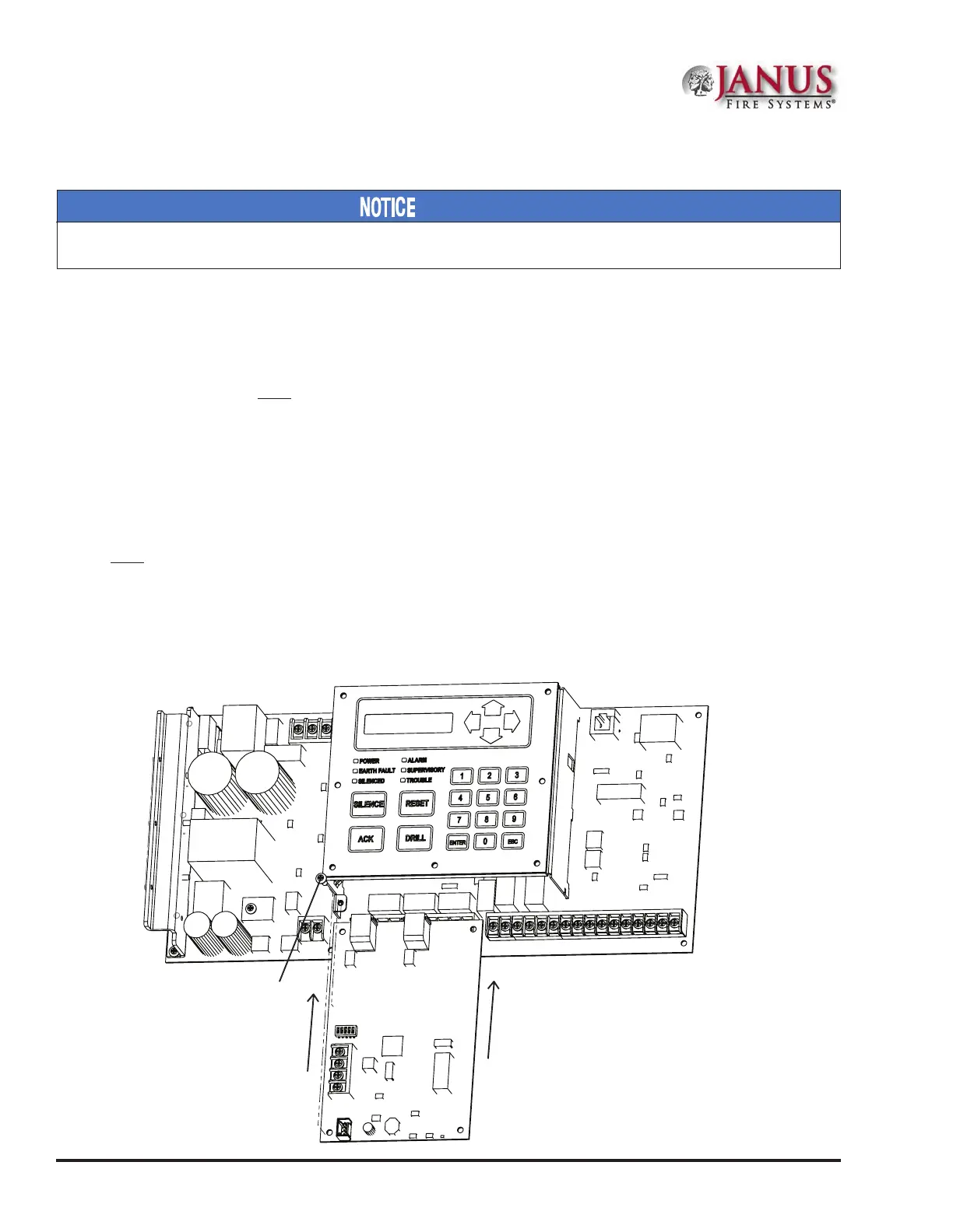
e UD-1000 slides into the guides located at the bottom of the panel, and then secured with screws as shown in
the following illustration.
Figure 34. Example of an Installed UD-1000 Dialer
Slides in guides under main board.
Screw
DWG #593-32A
UD-1000 DACT
 Loading...