Page: 7
JFS-A1 INSTALLATION, OPERATION, AND INSTRUCTION MANUAL
Document # : DOC230
Issued: August 27, 2012
Revised: N/A
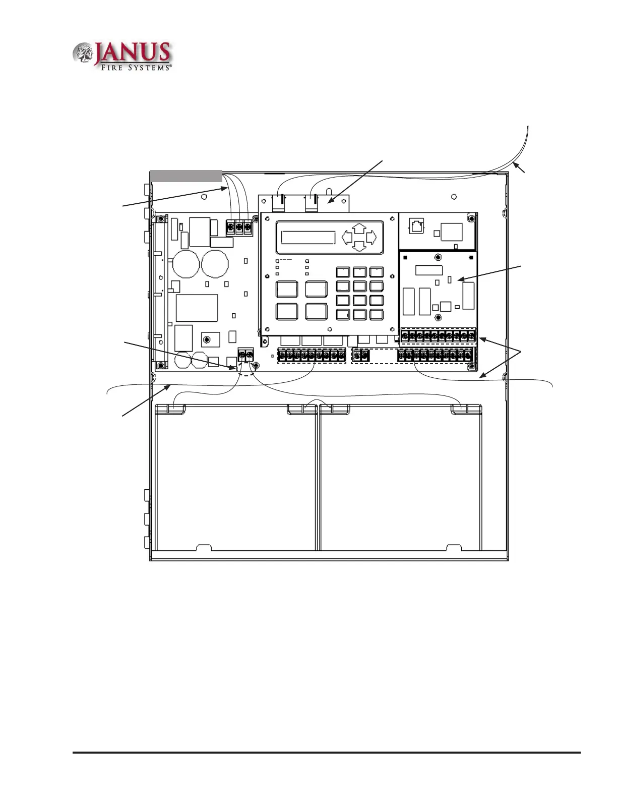
Cabinet Wiring Connections
Figure 2. JFS-A1 Cabinet Wiring
POWER
EARTH FAULT
SILENCED
ALARM
SUPERVISORY
TROUBLE
SILENCE
ACK
RESET
DRILL
1
2
3
4
5
6
7
8
9
0
ENTER
ESC
18Ahr 12Volt
18Ahr 12Volt
DWG # 593-2
DWG #593-2
Non-power
limited battery
connection
120VAC 50Hz-60Hz
240VAC 50Hz-60Hz
Connect to separate
unswitched AC circuits
High voltage
phone connections
Non-power
limited relay
connection
Optional
UD-1000 DACT
Optional CA-6075
Class A Expander
Power limited
wiring
Battery Circuit Calculations
Before selecting the battery, it is important to determine the minimum size batteries for standby and alarm times
desired for each application and SLC current draw. If the wrong batteries are installed in a specic application or
incorrect current draw used, the proper standby and minimum alarm time will not be present.
e battery circuit is rated for 8 to 55 AH batteries and will operate the panel alarm for at least 24 hours and
5minutes. e cabinet will house up to two (2) 8 AH or two (2) 18 AH batteries.
Please use the worksheets listed below to calculate the battery size and current draw required for each application
and the SLC:
1. Battery Calculation Worksheet
2. SLC Current Draw Worksheet