Page: 8
JFS-A1 INSTALLATION, OPERATION, AND INSTRUCTION MANUAL
Document #: DOC230
Issued: August 27, 2012
Revised: N/A
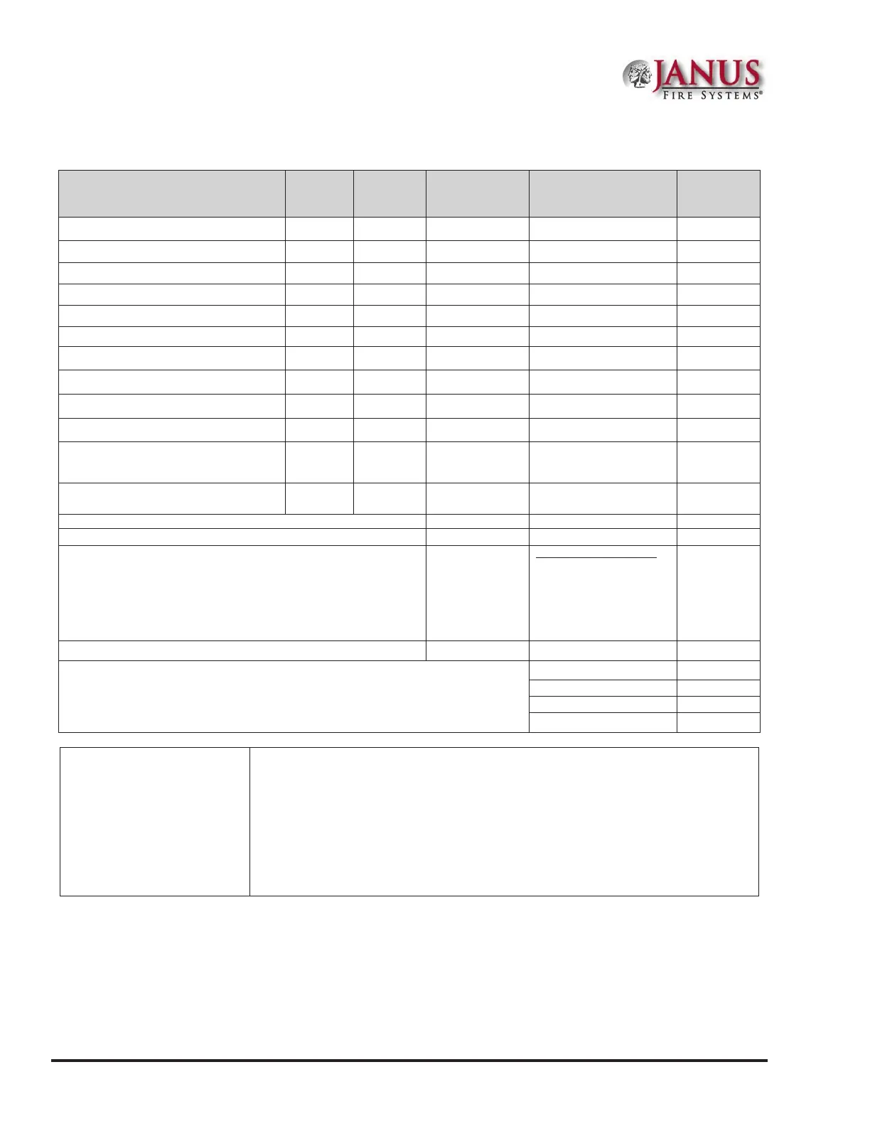
Battery Calculation Worksheets
Description Quantity
Standby
(mA)
Total
Standby (mA)
Alarm
(mA)
Total
Alarm (mA)
Main board (JFS-A1) 1 130 220
LCD Remote RA-6075R or RA-6075 20 25
LCD Remote RA-6500R 20 50
CA-6075 Class A Expander 12 44
UD-1000 DACT 16 23
PSN-1000/E Power Expander 15 15
NAC 1
NAC 2
I/O 1
I/O 2
SLC Current Draw - (refer to "SLC
Current Draw Worksheet" for
calculation)
Total (ma) Total ma
Convert to Amps x 0.001 Convert to Amps x 0.001
(*Refer to maximum allowable standby current) Total A: Total A:
Multiply by standby hours x____
60 minutes per hour
Alarm time (minutes)
Example:
5 minute alarm: enter
12 10 minute alarm:
enter 6
÷ ____
Total Standby AH Total Alarm AH
+Total Standby AH
Total AH
Efciency Factor ÷ 0.85
Required AH
*Maximum Allowable Standby
Current
(UL 24-Hour standby time)
7 AH .230 A
18 AH .619 A
33 AH 1.151 A
55 AH 1.930 A
Important Notes:
1) FACP enclosure can house up to two (2) 18 AH batteries. Larger batteries require
accessory enclosure, part #SSU00500.
2) NFPA 72 requires 24 hours of standby power followed by 5 minutes alarm activation.
3) NFPA 12, 12A requires 24 hours and ve minutes of alarm activation.
4) Door holder circuits congured to disconnect upon AC loss need not be included in
the battery standby calculation since they will not draw power during that time. Door
holders will contribute to standby current draw when AC is present.
5) Total current must not exceed power supply rating (5A).