Page: 13
JFS-A1 INSTALLATION, OPERATION, AND INSTRUCTION MANUAL
Document # : DOC230
Issued: August 27, 2012
Revised: N/A
Section 3: Installation
is section addresses installation procedures for SLCs, NACs and several optional modules, including the DACT
(UD-1000), Class A Card, and Remote Annunciators. Wiring requirements and conguration examples are included
throughout this section. Instructions for addressing SLC devices which must be completed before programming
your system are also included. Please read this section carefully before installing devices and/or modules to insure
proper installation.
Note: Instructions for installing the PSN-1000/PSN-1000(E) and/or the IP Dialer accessories are located in
Sections 6 and 7, respectively.
SignalingLineCircuit(SLC)Installation
e SLC panel provides power and communication to each of the sensors and modules connected. e SLC is
polled by the system every 4–5 seconds. is panel has a loop capacity of 75 addressable points, which may be
congured in any combination of smoke sensors, heat detectors, and input or output modules.
SLC Wiring Requirements
e wiring parameters listed below MUST be followed to ensure proper installation:
•y Maximum wiring resistance between two (2) Short Circuit Isolators (SCIs) must be less than 10 ohms.
•y Total resistance must be below 50 ohms.
•y Maximum wire resistance must be calculated based on 0.1 ohm per SCI.
•y Maximum loop capacitance must be 0.5 micro farads.
•y All SLC wiring is low voltage and power limited.
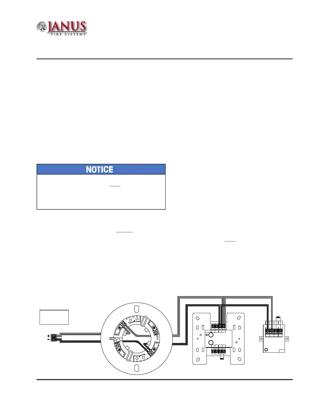
ClassB,Style4WiringConguration
Figure 7. Example of SLC Wiring - Class B, Style 4
S- S+ C
NO
(NC)
Potter Electric Signal Company
Miniature Contact Module
Model No. MCM
Ser. No. xxxxxx
Document:
TN51314e date: XX.XX.2009
WARNING:
All Terminals are power limited
Address No.
SIGNALING
LISTED
L
U
FIRE ALARM EQUIPMENT
XXXX
Address No.
Potter Electric Signal Company
FIRE ALARM EQUIPMENT
XXXX
24- 24+ S- S+
B- B+ A- A+
Conventional Initiating Zone Module
Model No. CIZM-4
Ser. No. xxxxxx
Document: TN51313e date:XX.XX.2009
Compatibility Identier: INTE01
WARNING :
Power supply for terminals 24+ and 24- must
be power limited
All Terminals are power limited.
SIGNALING
LISTED
L
U
PFC-6000
Series
SLC Loop (Class B)
Terminal Connections
3
6
7
8
5.1kΩ
5.1kΩ
DWG # 593-7A
All devices require an address prior to connecting to
the control panel. Refer to “Addressing SLC Devices”
located later in this section for details.