Page: 34
JFS-A1 INSTALLATION, OPERATION, AND INSTRUCTION MANUAL
Document #: DOC230
Issued: August 27, 2012
Revised: N/A
Section 4: Operation
is section provides an overview of the control panel’s basic operations, which includes the status LEDs, function
pushbuttons, and a Control Panel Menu Tree quick reference sheet.
Control Panel Basic Operation
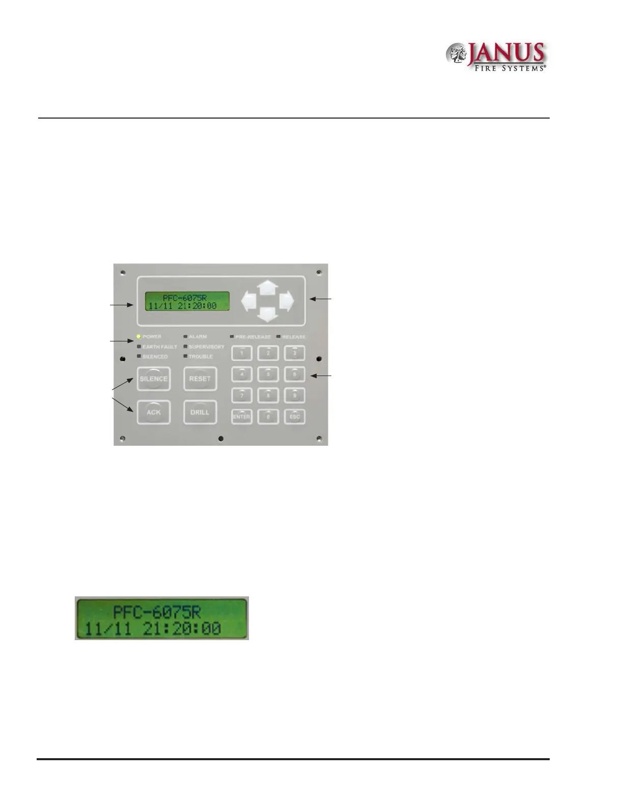
e control panel is comprised of a two (2) line x 16-character LCD display panel, arrow keys, push button function
keys, status LEDS, and the numeric keypad. A description of each component is included in this section, and refer
to the gure below for an example.
Figure 37. JFS-A1 Control Panel Display
Note: Authorized system operators must use a key to open the outer door of the cabinet.
LCD Display
e LCD panel displays the standard Start-up menu as shown below. e LCD displays up to thirty-two (32)
characters of information displays, providing important feedback to system users, i.e., system messages, status
information, trouble conditions, or input changes. e LCD also provides access to the Main Menu for daily system
operations and specic programming functions (refer to “Section 5: Programming – Menu Functions” for details on these
topics).
Figure 38. LCD Start-Up Screen
Note: You may customize the Start-up screen to display a specic job site name or other relevant descriptive
text.
Status
LEDs
Numeric Keypad
Arrow Keys
Function
Pushbuttons
LCD
Display