Page: 29
JFS-A1 INSTALLATION, OPERATION, AND INSTRUCTION MANUAL
Document # : DOC230
Issued: August 27, 2012
Revised: N/A
P-Link Devices
Accessory devices, such as remote annunciators, are connected to the main control panel utilizing the four-wire
P-Link bus for power and communication. Devices can be connected using a Class B or Class A wiring style
(examples are provided throughout this topic).
Note: If you have chosen to install an optional PSN-1000/PSN-1000(E), power expansion board, refer to Section 6:
PSN-1000/PSN-1000(E) – Installing, Operating & Programming, for instructions on installing this
appliance.
CongurationCharacteristics
y P-Link current rating is one (1) amp.
y P-Link voltage rating is 24 VDC.
y e maximum wire length is 6,500 feet.
Maximum Wire Resistance Formula
e maximum resistance is based on the load placed on the circuit. To calculate the maximum wire resistance, use
the following formula:
(Total Annunciator Alarm Current) x (Wire Resistance) < 6 Volts
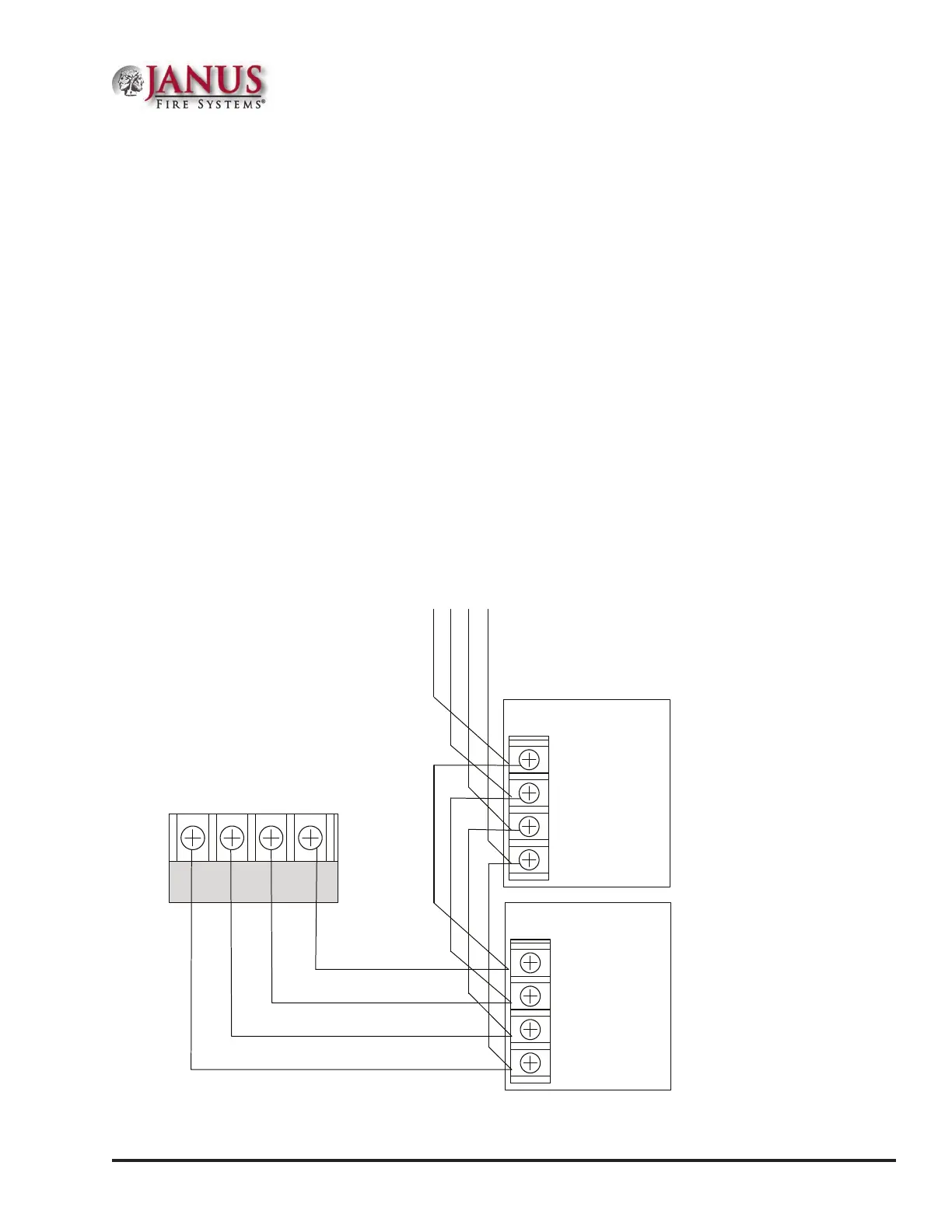
Figure 31. P-Link Class B Wiring Example
To the next device
- + A B
Expansion
Device
- + A B
P-LINK
- + A B
Panel
Connection
Expansion
Device
DWG #602-11A