Page: 19
JFS-A1 INSTALLATION, OPERATION, AND INSTRUCTION MANUAL
Document # : DOC230
Issued: August 27, 2012
Revised: N/A
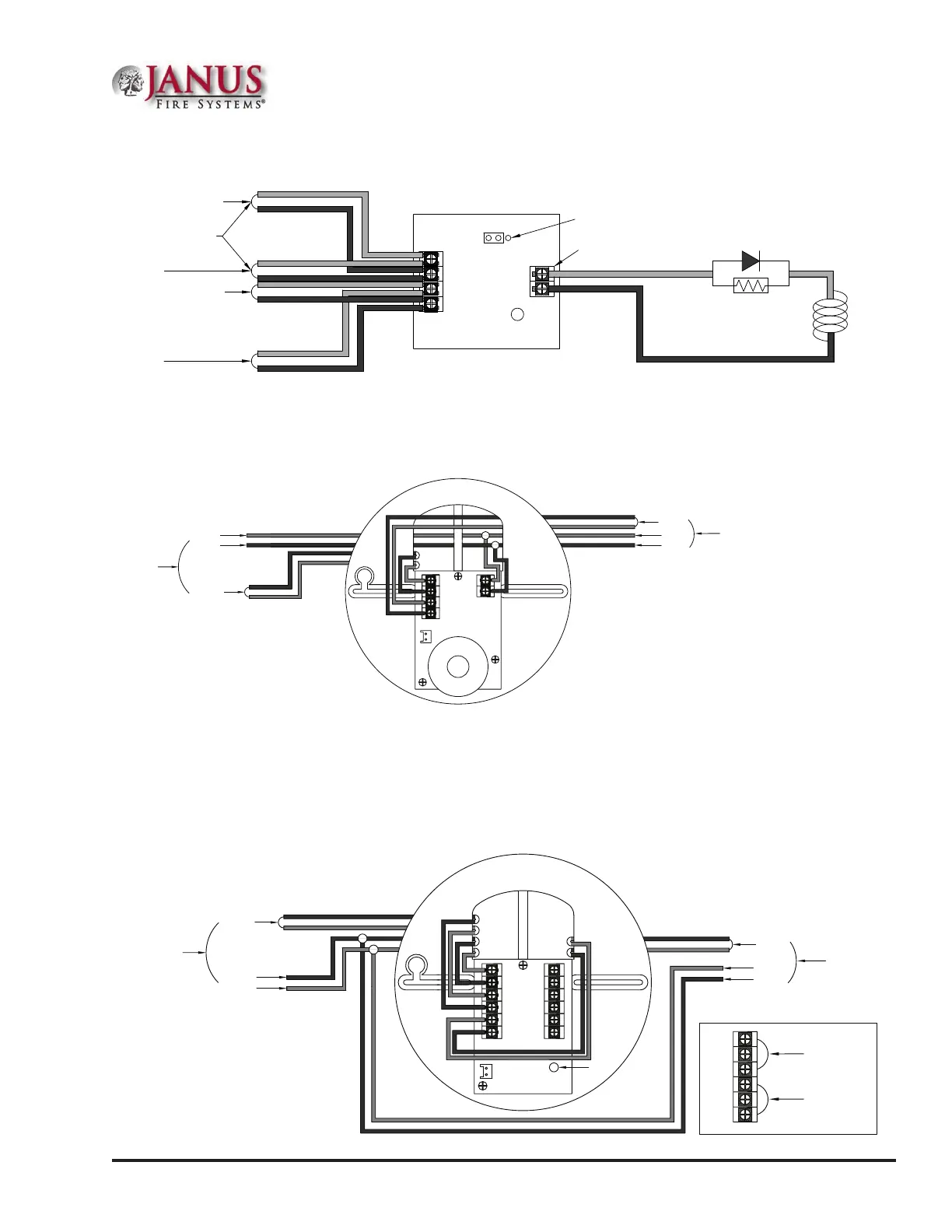
Figure 19. Example of MOM-4 Wiring as a Releasing Device
ConnectingAnalogSounderBase(ASB)
Figure 20. Example of Analog Sounder Base Wiring
Notes:
1. e supply power must be coded in order for the output to be coded.
2. ASB does not generate a coded output. It will track the pattern delivered to its 24VDC input.
ConnectingAnalogRelayBase(ARB)
Figure 21. Example of Analog Relay Base Wiring
Monitored Output Module
Model No. MOM-4
From FACP or Previous Module
To Next Module
From FACP or Previous Module
To Next Module
24-
24+
S-
S+
A-
A+
SLC Loop
LED
JP1
Select DC
Output Rating:
24VDC / 2.0A
Releasing
Device
End of Line Device
5.1Kohm 1/2W
Part#3005012
Note:
EOL Device shall be installed in the same
electrical enclosure as the releasing device
DWG #602-35
Analog Sounder Base
Model No. ASB
S-
S+
S+
S-
TB1
24+
24-
S-
S+
SLC Loop
24 VDC-
24 VDC+
From FACP or
Previous Module
SLC Loop
24 VDC+
24 VDC-
To Next Module
DWG #593-19
To Next Module
Analog Relay Base
Model No. ARB
S-
24+
S+
24-
S+
S-
NO2
NO1
NC1
C1(8A)
C2(2A)
NC2
TB1 TB2
SLC Loop
24 VDC+
24 VDC-
From FACP or
Previous Module
SLC Loop
24 VDC+
24 VDC-
LED
NO2
NO1
NC1
C1(8A)
C2(2A)
NC2
TB2
8.0A / 240VAC
8.0A / 30VDC
2.0A / 240VAC
2.0A / 30VDC
DWG #593-20

 Loading...