Page: 67
JFS-A1 INSTALLATION, OPERATION, AND INSTRUCTION MANUAL
Document # : DOC230
Issued: August 27, 2012
Revised: N/A
Mapping Terminology
e table below provides mapping terms that may be helpful to you in understanding the mapping concept:
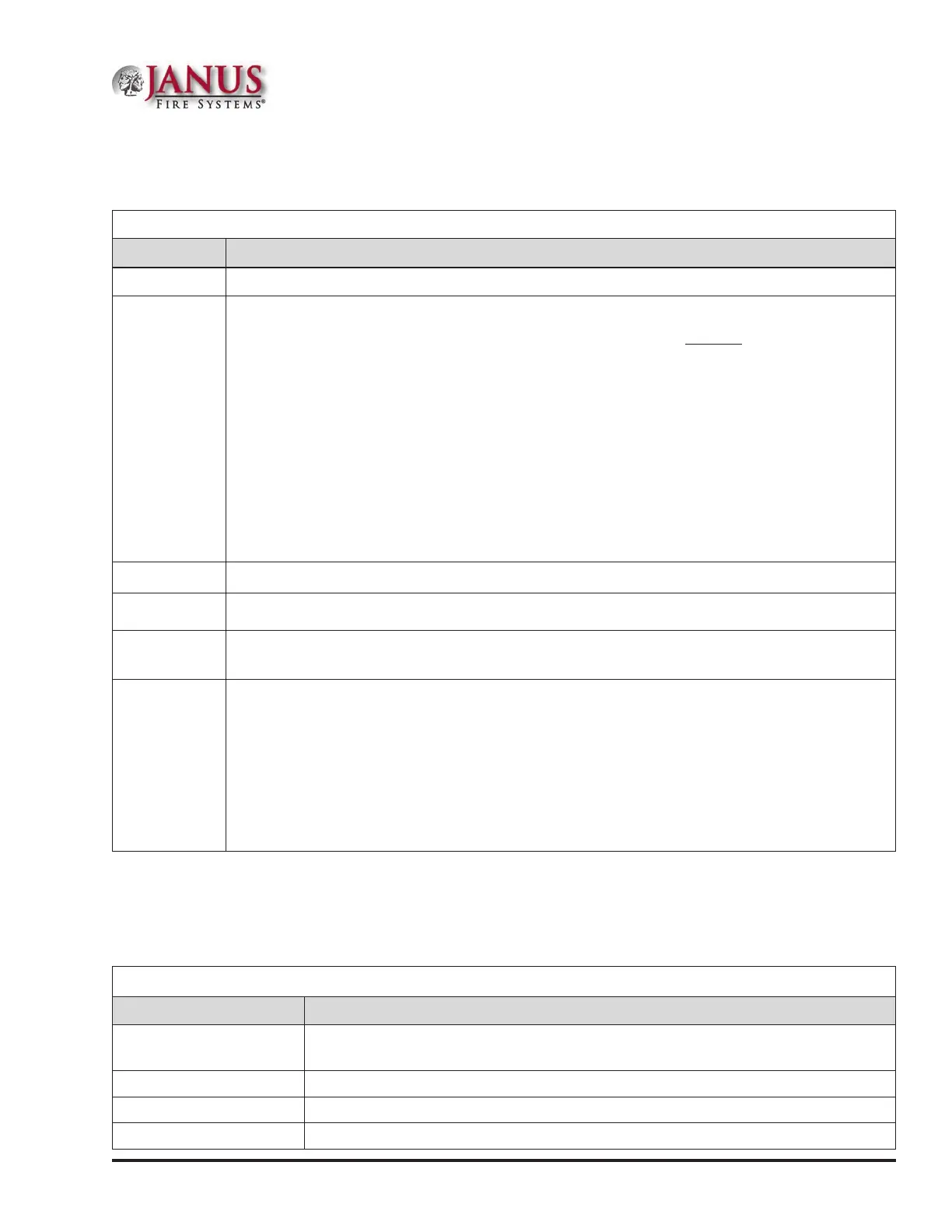
Table 15: Mapping Terminology
Term Denition
Mapping Creating relationships between devices, modules and sensors and dening their behavior.
Zone
A group of devices.
Zones may represent a group of devices located in a specic physical area at the site.
Example: Zone 1 comprised of all devices located in the main lobby of a hotel, [i.e., pull
station #1, one (1) sounder base, and one (1) strobe-NAC].
Zones may represent a set of devices congured for a specic function; their location may
be scattered throughout the site. This group is a “logical” grouping or zone.
Example: Zone 2 comprised of all devices in Zone 1 as described above, plus a 2
nd
pull
station located at end of a hallway and two (2) additional Sounder bases.
Notes:
1. If all input / output devices are grouped into one (1) zone, when any input is activated, all
outputs activate.
2. A device or point may be mapped into more than one (1) zone.
Point Any specic device, module or appliance connected to panel.
Latching Device will not automatically reset; device must be RESET at the keypad to remove condition.
Non-Latching
Device will automatically reset when condition is no longer present, i.e., smoke detector resets
once condition clears.
Cross Zoning
The purpose of creating cross zones is to ensure that two (2) or more separate zones are
activated before an output zone is triggered.
Example: Smoke detector in Zone 1 (R&D Lab), and a heat detector in Zone 2 (Main entrance)
are activated, triggers an air handler circuit.
The redundancy in this example provides verication of an alarm condition by requiring that
both sensors in two (2) different zones are activated before an output occurs.
There are no limits to the number of cross zones that can be mapped to the same output;
as soon as a pair of input devices detects an “alarm” condition, the output will be activated.
ZoneTypes/Styles
You may dene or congure each zone to serve a specic purpose or to create specic output results. For procedures
on how to select Zone styles, refer to the “Conguring Zones” section of this manual. e following zone styles are
available:
Table 16: Zone Styles
Zone Description
Alarm
•y Default zone type.
•y Sets system into an Alarm condition when any input is activated.
Supervisory Used for all Supervisory inputs.
Positive Alarm Sequence Implements Positive Alarm Sequence.
Auxiliary Used for all “Aux” inputs.