Page: 5
JFS-A1 INSTALLATION, OPERATION, AND INSTRUCTION MANUAL
Document # : DOC230
Issued: August 27, 2012
Revised: N/A
ElectricalSpecications
Please refer to the table below for electrical specications:
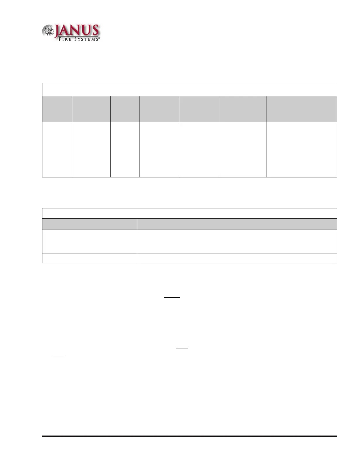
Table 3: SystemPanelElectricalSpecications
Panel # NACs
Rating
per
NAC
I/O Circuits
(As
Outputs)
SLC Power Notes Style and Class
JFS-A1
2 up to 4 if
both I/O
circuits
congured
as NACs
3 Amp 1 Amp
Maximum
Load of
56.055 mA
Maximum
of 75
addressable
points
SLC – Class A or B
NAC – Class A or B
P-Link – Class A or B
I/O – Class B only
All are Low Voltage
and Power Limited
SystemSizeSpecications
Please refer to the table below for system size specications:
Table 4: SystemSizeSpecications
Accessories/Subassemblies Maximum System Size
JFS-A1
•y One (1) built-in SLC Loop with 75 addressable points
•y Two (2) notication/releasing circuits on the main board
•y Two (2) I/O circuits
UD-1000 One (1) DACT
MainBoardWiringSpecications
ere are several wiring requirements to consider before connecting circuits to the main board: (1) the circuit separation,
and (2) wiring types.
Circuit Separation
Proper separation between the dierent types of circuits must be maintained between Power Limited, Non-Power
Limited, and High Voltage wiring to reduce electrical interferences, transient voltage or voltage ratings.
y Separations between the dierent wiring types must be maintained by at least ¼inch and the wire insulation
must be for the higher voltage.
y e control panel cabinet has sucient knockouts located around the periphery allowing the installer to maintain
separation between power limited and non-power limited connections.

 Loading...