Page: 10
JFS-A1 INSTALLATION, OPERATION, AND INSTRUCTION MANUAL
Document #: DOC230
Issued: August 27, 2012
Revised: N/A
Isolator Device Load Calculation
is section covers the distinction between an addressable sensor and an isolator to correctly calculate the total SLC
device load. A device uses an address and consumes power. Whereas, an isolator does not use an address, but does
consume power.
e following scenarios explain how to calculate the current device load based on the SLC conguration.
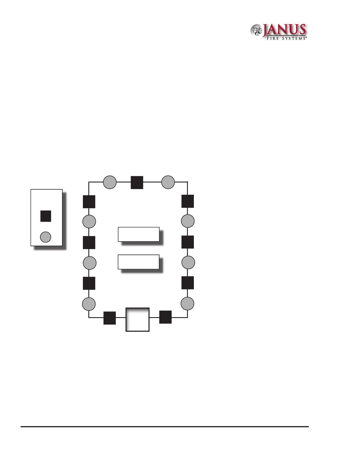
Scenario1:ClassALoop–IsolatedDevicesConguration
In this conguration, each sensor and isolator device / module counts as one (1) when calculating the total device
load.
Formula: Total # addressable devices + Total # isolators = Total power unit allocations (or device load)
Figure 3. Example of a Class A Loop – Isolated Branches
Conguration Summary:
Total addressable devices = 8 (sensors only) out of 75 possible addressable points.
Total device load = 17 (calculated as follows: 8 sensors + 9 isolators) out of 127 power unit allocations.
Example: If a conguration uses 75 sensors, up to 52 isolators may be supported.
Solution: 127 - 75 = 52
LEGEND:
ISO Module/
Device
Sensor
PANEL
Total addressable
devices = 8
Total isolators = 9
DWG # 593-4