Page: 66
JFS-A1 INSTALLATION, OPERATION, AND INSTRUCTION MANUAL
Document #: DOC230
Issued: August 27, 2012
Revised: N/A
System Programming
System programming involves dening the function of devices and their relationships to each other, referred to as
mapping. You can dene behavior characteristics of individual or groups of devices, map devices into zones, and
further customize your system using the panel conguration software from a computer.
e panel conguration software features include:
y Easy to use Windows-based editing techniques, including drag and drop between windows.
y Flexibility in conguring points into multiple zones promoting sophisticated mapping relationships.
y Simple sorting and grouping by select elds enhances viewing and analysis of data.
y Options to view points by type, address and function or description.
Mapping Zones Overview
Mapping is creating relationships between devices, modules and sensors and their behavior between each other.
Whereas, the “zone” is the framework in which you group the devices. ese terms and other related mapping
concepts are provided in this section.
Single Zones
e LEARN feature creates or maps a basic, one-to-one relationship where all devices are automatically grouped
into one zone. When all devices are in the same zone, and an input device is activated, all output devices will activate.
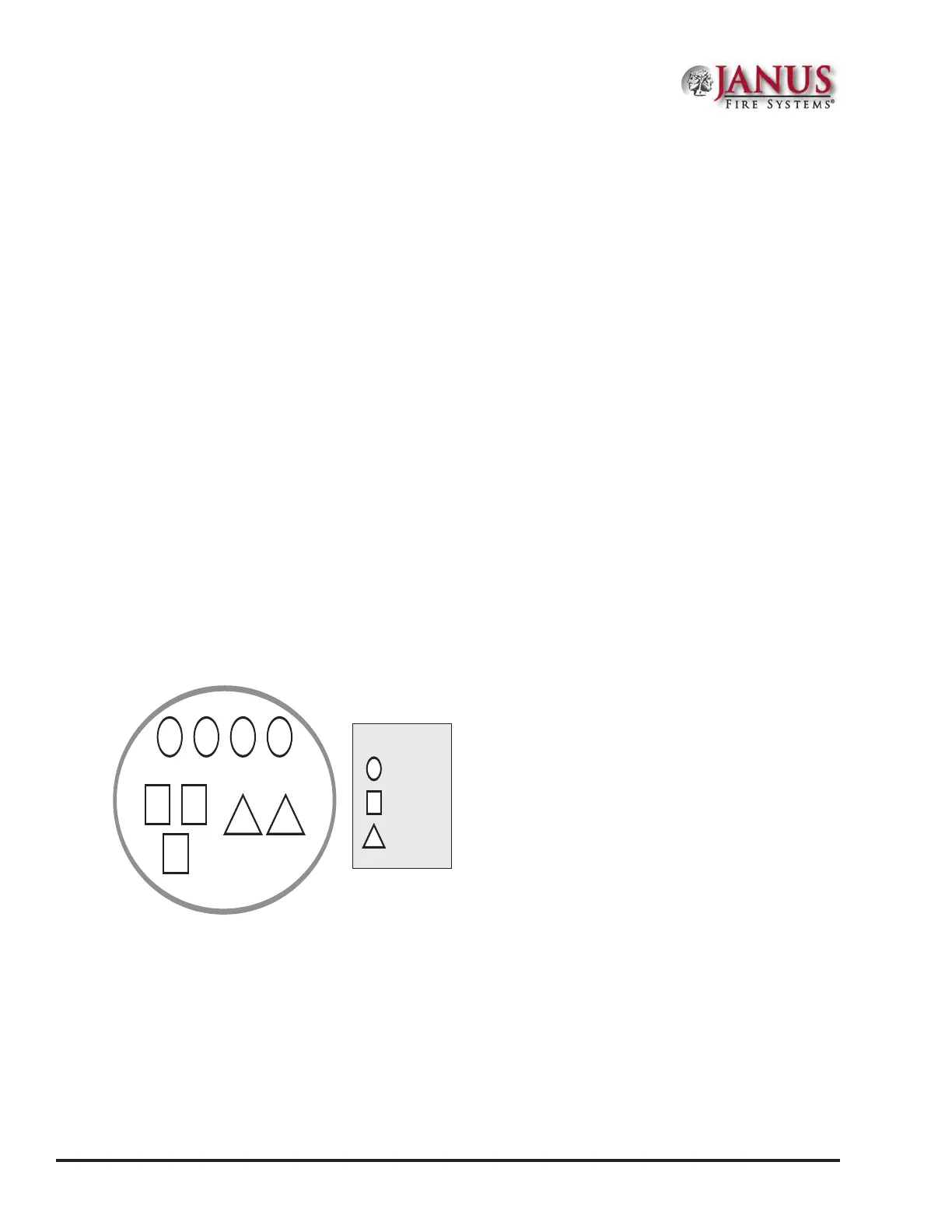
Please refer to the illustration below for an example of a one-to-one device relationship:
Figure 79. Mapping all Devices to One Zone
Zone 1
1 2 3 4
5 6
7
P-2 P-1
Symbol Legend:
= SLC Input
= SLC Output
= Panel Hardware
Multiple Zones
e panel conguration software allows you to customize the operational mode behavior of devices by grouping
them into a maximum of 99 dierent zones. All SLC devices, including the four (4) on-board circuits (I/Os 1 and
2, and NACs 1 and 2), may be congured to behave in a specic manner. is exibility enables you to congure
system points to maximize protection throughout your site.
By organizing devices into dierent zones, you can create unique relationships between devices for specic outputs
or events. e panel conguration software allows you to eciently group points to follow a sequence of events
producing the same combination of outputs into dierent zones. is section addresses how to accomplish these
tasks.