Page: 22
JFS-A1 INSTALLATION, OPERATION, AND INSTRUCTION MANUAL
Document #: DOC230
Issued: August 27, 2012
Revised: N/A
NoticationApplianceCircuitsInstallation
ere are two (2) NAC circuits provided on the JFS-A1 rated as continuous 3amps at 24 VDC. e NAC circuits
may be congured for Class A or Class B. (Please refer to the Class A and B wiring examples located in this section.)
NAC Wiring
y Outputs are supervised and regulated.
y Circuits are power limited.
y Type of NAC output is selectable, and may be congured for strobe synchronization with Potter/AMSECO,
Cooper Wheelock®, Gentex®, or System Sensor® strobe devices. Refer to the listing of compatible models
located in the “NAC Compatibility Document”, Potter #5403592, for this information.
y e CA-6075 Class-A Expander may be programmed to allow for operation of the NACs. e expander
adheres to the same circuit rating, supervision and regulation as other circuits.
NAC Maximum Wiring Impedance Formula
e maximum impedance is a function of the load placed on the circuit. To calculate the maximum line current
impedance, use the following formula:
(Alarm Current of Notication Appliances) x (Wire Resistance) < 3 Volts
NACWiringCongurations
Examples of ClassB and Class A Wiring follow.
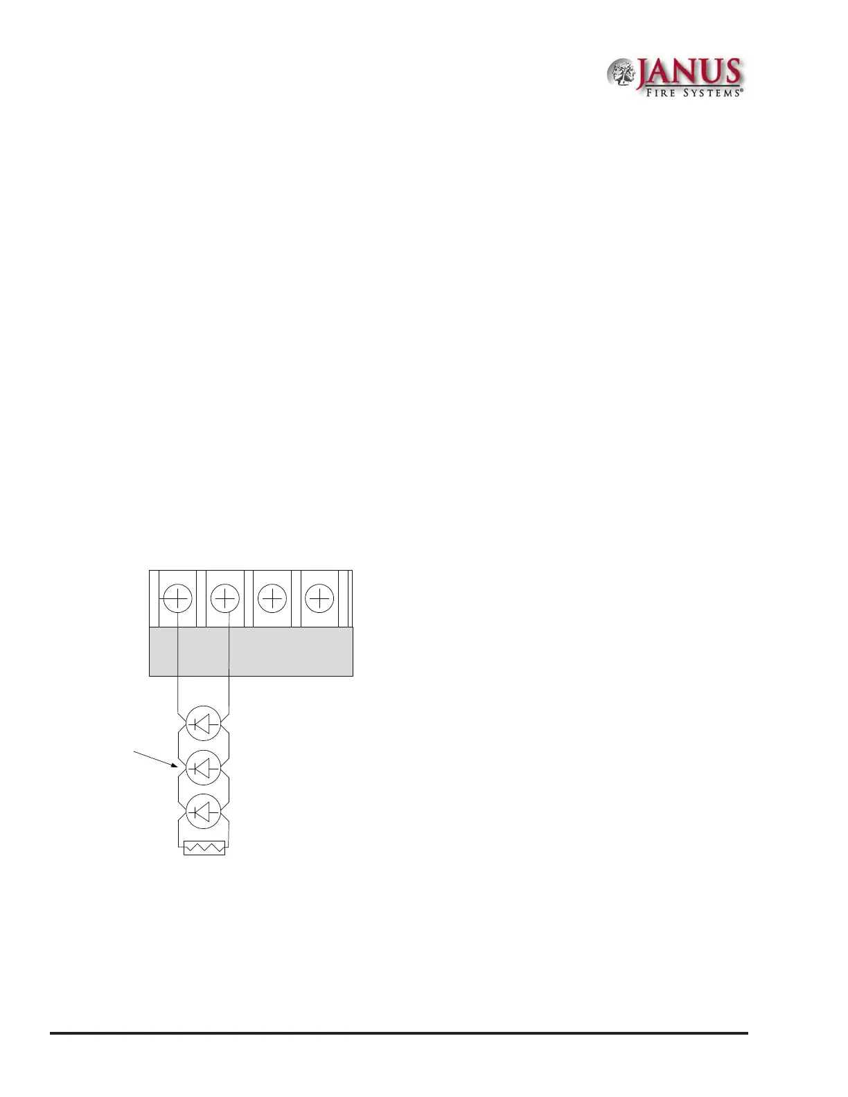
Figure 23. NAC Class B Wiring Example
NAC 1 NAC 2
- + - +
5.1k EOL
Potter Part #3005013
Notification
Appliance
Notes:
1. e Potter part number for the listed end of line assembly is #3005013 EOL Resistor Assembly.
2. e panel has ground fault detection on the NAC circuits. e impedance to ground for ground fault
detection is 0 ohms.
DWG #602-4A