Page: 26
JFS-A1 INSTALLATION, OPERATION, AND INSTRUCTION MANUAL
Document #: DOC230
Issued: August 27, 2012
Revised: N/A
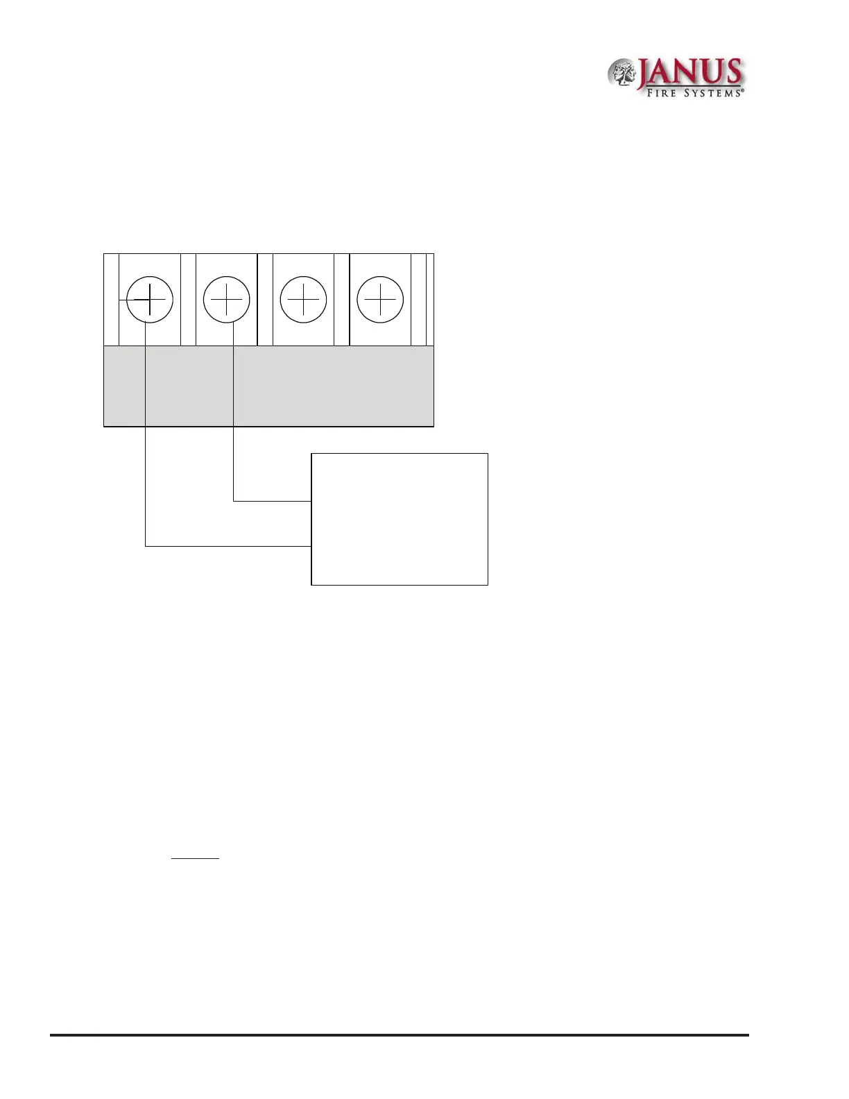
Reverse Polarity Communication Line Circuit
Only I/O 1 and I/O 2 on the JFS-A1 can be programmed as reverse polarity circuits. e short circuit current is
rated at 24 VDC and 14 mA maximum. Please refer to the gure below for an example of wiring a reverse polarity
communication line circuit.
Figure 27. Reverse Polarity Communication Line Circuit Wiring
Notes:
1. e panel has ground fault detection on reverse polarity circuits; impedance to ground for ground fault detection
is 0 ohms.
2. e short circuit current is power limited and supervised by a Keltron TTM-RPS transmitter module.
3. When congured for reverse polarity, the JFS-A1 will indicate alarm and trouble events to a remote site.
4. e Alarms override trouble conditions.
DWG #602-8A
Panel
Connection
I/O 1 I/O 2
- + - +
Keltron
TTM-RPS
+
-
Note: IO circuit must configured as a Reverse Polarity circuit.
This connection is limited to same room installation . This connection shall be
limited to 20 feet and enclosed in conduit or equivalently protected against
mechanical injury.