Page: 15
JFS-A1 INSTALLATION, OPERATION, AND INSTRUCTION MANUAL
Document # : DOC230
Issued: August 27, 2012
Revised: N/A
From FACP or the previous
addressable device on the SLC loop
To the next addressable device
S+ S+
S- S-
DWG #593-10
ClassA,Style7WiringConguration
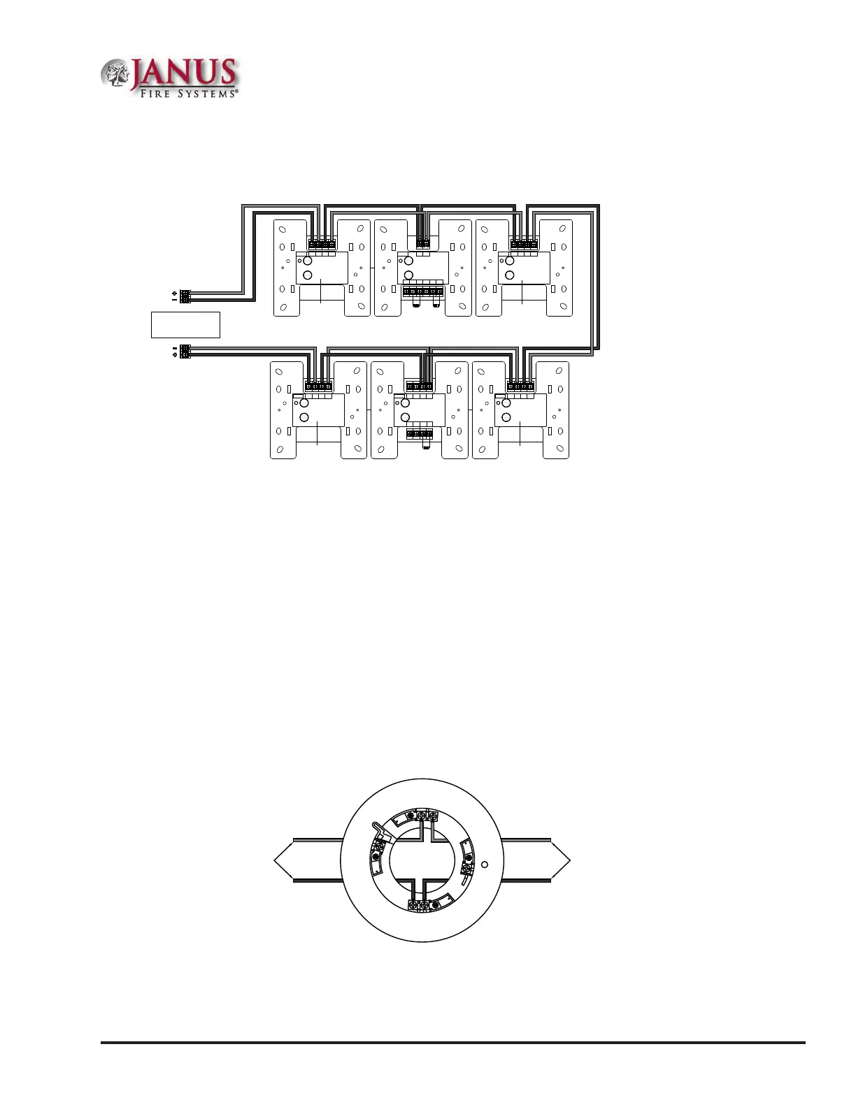
Figure 9. Example of SLC Wiring - Class A, Style 7 Requiring CA-6075
Address No.
Potter Electric Signal Company
FIRE ALARM EQUIPMENT
XXXX
Address No.
Potter Electric Signal Company
FIRE ALARM EQUIPMENT
XXXX
24- 24+ S- S+
B- B+ A- A+
Conventional Initiating Zone Module
Model No. CIZM-4
Ser. No. xxxxxx
Document: TN51313e date:XX.XX.2009
Compatibility Identier: INTE01
WARNING :
Power supply for terminals 24+ and 24- must
be power limited
All Terminals are power limited.
S- S+
Z2 C2 Z1 C1
NO2
(NC2)
NO1
(NC1)
Dual Contact Module
Model No. DCM-4
Ser. No. xxxxxx
Document: TN51316e date:XX.XX.2009
WARNING :
All Terminals are power limited.
SIGNALING
LISTED
L
U
SIGNALING
LISTED
L
U
PFC-6000
Series
SLC Loop (Class A Style 7)
Terminal Connections
5.1kΩ 5.1kΩ
5.1kΩ
Address No.
Potter Electric Signal Company
FIRE ALARM EQUIPMENT
XXXX
S-1 S+1
Short Circuit Isolater
Model No. SCI
Ser. No. xxxxxx
Document: TN51313e date:XX.XX.2009
WARNING :
All Terminals are power limited.
SIGNALING
LISTED
L
U
S-2 S+2
Address No.
Potter Electric Signal Company
FIRE ALARM EQUIPMENT
XXXX
S-1 S+1
Short Circuit Isolater
Model No. SCI
Ser. No. xxxxxx
Document: TN51313e date:XX.XX.2009
WARNING :
All Terminals are power limited.
SIGNALING
LISTED
L
U
S-2 S+2
Address No.
Potter Electric Signal Company
FIRE ALARM EQUIPMENT
XXXX
S-1 S+1
Short Circuit Isolater
Model No. SCI
Ser. No. xxxxxx
Document: TN51313e date:XX.XX.2009
WARNING :
All Terminals are power limited.
SIGNALING
LISTED
L
U
S-2 S+2
Address No.
Potter Electric Signal Company
FIRE ALARM EQUIPMENT
XXXX
S-1 S+1
Short Circuit Isolater
Model No. SCI
Ser. No. xxxxxx
Document: TN51313e date:XX.XX.2009
WARNING :
All Terminals are power limited.
SIGNALING
LISTED
L
U
S-2 S+2
DWG #593-9
SCI
SCI
SCI
SCI
Notes:
1. e Class A, Style 7 requires installation of an isolator close nipple connected to every module or sensor.
Isolators may be either a SCI or an AIB addressable base.
2. Class A, Style 7 requires installation of a CA-6075.
3. e SLC connection requires that the wires are separated by a minimum of 10’ and installed in conduit or
other mechanical protection.
4. Maximum wiring resistance must not exceed 50 ohms.
Connecting Analog Detectors
When installing analog detectors, such as a photoelectric smoke sensor (PSA), photo smoke/xed heat detector
(PSHA), heat detector (FHA), or an analog combination type heat detector (RHA), use detector bases (i.e.AB-6).
An analog detector activates its response LED when activated. An example of wiring an analog detector is shown
below.
Figure 10. Analog Detector Wiring Example

 Loading...