Page: 27
JFS-A1 INSTALLATION, OPERATION, AND INSTRUCTION MANUAL
Document # : DOC230
Issued: August 27, 2012
Revised: N/A
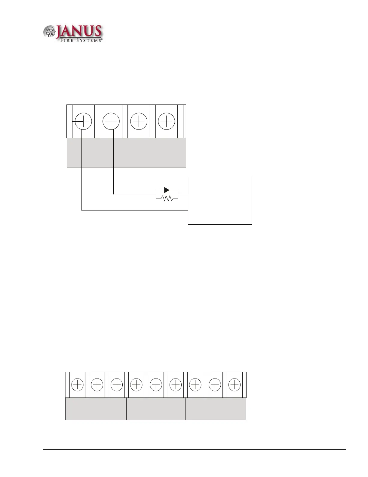
Municipal Box Connection
When programmed as a municipal box connection, the circuit power is limited, supervised for open and short circuit
conditions, and provides a local energy connection.
Figure 28. Municipal Box Wiring Example
Notes:
I/O circuits and/or NAC Circuits can be used as Municipal
Box connection.
The EOL device shall be installed in the same electrical enclosure as the Municipal Box.
Panel
Connection
I/O 1 I/O 2
- + - +
Municipal
Box
+
-
End of line device
5.1k ohm 1/2W
Part #3005012
Notes:
1. e trip current for NAC1 and NAC2 is three (3) Amps, and one (1) Amp for I/O1 and I/O2.
2. e maximum voltage rating is 24 VDC.
3. e panel has ground fault detection on municipal box connection circuits. e impedance to ground for
ground fault detection is 0 ohms.
Relay Output Wiring
e panel has three (3) dedicated common relays. e dedicated trouble relay is a fail safe trouble relay that changes
position anytime a trouble condition occurs.
Relays have a contact rating of 24VDC / 3.0A, 125VAC / 3A, and Power Factor of 1.0. ese outputs are non-power
limited and not supervised.
Note: If the power supply connected to the devices is power-limited, then the outputs are power limited.
Figure 29. Relay Outputs
TROUBLE
NC COM NO
SUPERVISORY
NC COM NO
ALARM
NC COM NO
DWG #602-9A
DWG #593-26